2022年1月31日星期一
Induction Brazing Steel Tube
Induction Brazing Steel Tube
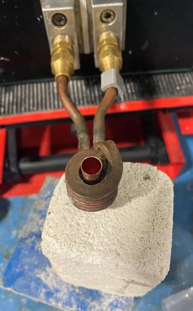
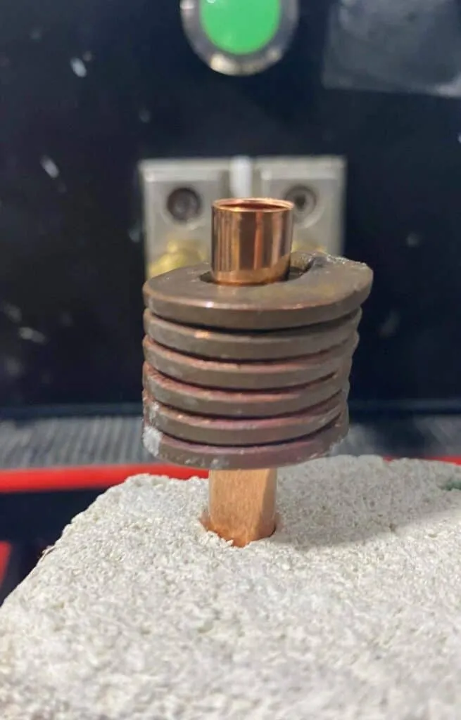
Objective: To heat an oil suction assembly (steel tubing and filter cap) to 1,850°F (1010°C) within 15 seconds for a brazing application.
Material 0.125" (3.2mm) diameter steel tube and filter cap assembly, high temperature brazing flux, copper ring.
Temperature 1850°F(1010°C)
Frequency 500 kHz
Equipment • DW-UHF-6KW-I induction heating system equipped with a remote workhead containing 0.66 μF capacitors • An induction heating coil designed and developed specifically for this application.
Process A two-turn, specially-contoured helical induction coil is used to heat the tube assembly near the joint area. A copper ring and high temperature flux are then applied to the joint area. Power is applied for 15 seconds until the braze flows.
Results/Benefits Induction heating provides:
• Easy loading and unloading of parts
• Heat very precise areas within production tolerances
• Hands free heating that involves minimal operator skill for manufacturing
Induction Shrink Fitting For Inserts
Induction Shrink Fitting For Inserts with IGBT Shrink fitting Heater
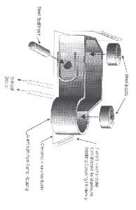
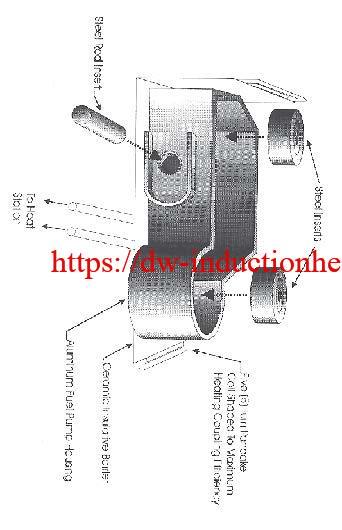
Objective: To heat an aluminum fuel pump housing measuring 8" x 4 1/2" x 3 1/2" to 3750F, allowing steel parts to be inserted. Presently the housings are heated for over one hour in a convection oven. The areas that are to have steel parts inserted measure 1.5" and 0.6875" in diameter. In addition, the insertion process lasts for a little over one minute, so 3750F should be maintained for a
period of time to complete the process.
Material: Aluminum Pump Housing measuring 8" x 4 1/2" x 3 1/2"
Steel insertion parts.
Temperature: 3750F
Application: By using the DW-HF- 25, 25 kW output solid state induction power supply the following results were achieved.
- 3750F was reached in one (1) minute to allow for insertion.
- 20 housings were successfully heated using a five (5) turn right angle pancake coil.
Equipment: Ameritherm SP 25, 25 kW output solid state induction power supply including one (1) remote heat station containing four (4) capacitors totalling 1.0 μF, and a five (5) turn right angle pancake coil made from 3/16" copper tube.
Frequency: 80 kHz
ultrasonic welding equipment | ultrasonic plastic welder for fabric
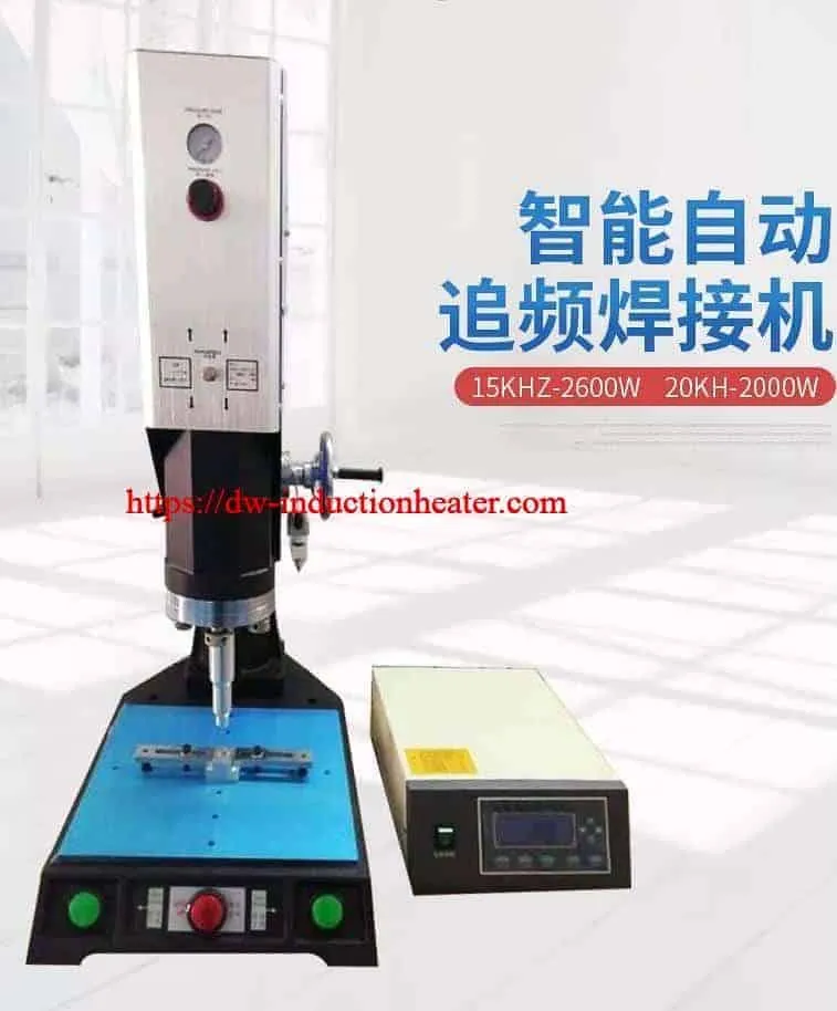
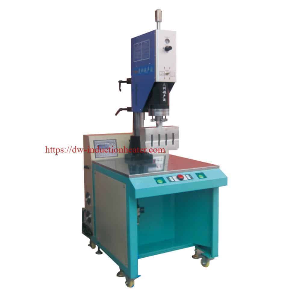
ultrasonic welding equipment | ultrasonic welder | ultra sonic plastic welder with Automatic Frequency Chasing
Ultrasonic welding is an industrial technique whereby high-frequency ultrasonic acoustic vibrations are locally applied to workpieces being held together under pressure to create a solid-state weld. ♦Fully automatic frequency chasing, suitable for various sizes of welding die and different design mold, automatic chasing frequency range:±400HZ
Example: 15KHZ ultrasonic, mold frequency in 14.4-15.2KHZ can Automatic frequency traceability
♦The use of CPU computer to monitor various programs is fast and adaptable. The built-in protection system "system protection monitoring" function will respond to the following situations: the temperature is too high and the pressure is too high, which leads to overload. Excessive current of ultrasonic generator, loosening of solder head, transducer or transducer, failure of generator circuit, etc.
♦Automatic tuning enables the ultrasonic generator to automatically track and compensate for changes in welding head frequency. When the temperature is too high, wear on the surface of the welding head or debris on the head, this frequency change will occur.
♦Built-in automatic constant amplitude system. The ultrasonic amplitude can be adjusted from 50% to 100% stepless to adapt to different welding work.
♦With IGBT, the reaction speed is 100 times faster than that of traditional silica gel power tube.
♦Fully automatic frequency chasing, suitable for various sizes of welding die and different design mold, automatic chasing frequency range:±400HZ
Example: 15KHZ ultrasonic, mold frequency in 14.4-15.2KHZ can Automatic frequency traceability
♦The use of CPU computer to monitor various programs is fast and adaptable. The built-in protection system "system protection monitoring" function will respond to the following situations: the temperature is too high and the pressure is too high, which leads to overload. Excessive current of ultrasonic generator, loosening of solder head, transducer or transducer, failure of generator circuit, etc.
♦Automatic tuning enables the ultrasonic generator to automatically track and compensate for changes in welding head frequency. When the temperature is too high, wear on the surface of the welding head or debris on the head, this frequency change will occur.
♦Built-in automatic constant amplitude system. The ultrasonic amplitude can be adjusted from 50% to 100% stepless to adapt to different welding work.
♦With IGBT, the reaction speed is 100 times faster than that of traditional silica gel power tube.
| Model | 1520A | 1526A | 1532A | 1542A |
| Frequency | 15KHz | |||
| Power | 2000W | 2600W | 3200W | 4200W |
| Voltage | 220V | |||
| Capacity | 10-20 times/min | |||
| Driving form | Pneumatic | |||
| Stroke Length(Horn Journy) | 75mm | 100mm | ||
| Output Time | 0.01-9.99S Adjustable | |||
| Welding Area | Φ100 | Φ200 | Φ300 | Φ400 |
| Electricity | AC | |||
| Control mode | Numerical control | |||
| Working air pressure | 1-7 Bar | |||
| Weight | 90KG | 90KG | 90KG | 120KG |
| Dimensions | 450*750*1100mm | 760*1000*1950mm | ||
 Main Features
1. Ultrasonic Welding Plastic Machine, manually tuning, simple to use and maintenance.
2. Welding by time, delay time, weld time and hold time. Working pressure is adjustable.
4. Precise and high quality imported pneumatic parts
5. High quality transducer and booster.
6. Self-protection: Over-Current, Frequency Deviation, Over-Temperature
7. Available in 4 frequencies – 15 KHz, 20 KHz ,35 KHz and 40 KHz.
8. Quick application changeover, high welding seam strength.
9. Suitable for high cadences and short cycle times.
Ultrasonic Welding Horns/Ultrasonic Welding Molds:
Main Features
1. Ultrasonic Welding Plastic Machine, manually tuning, simple to use and maintenance.
2. Welding by time, delay time, weld time and hold time. Working pressure is adjustable.
4. Precise and high quality imported pneumatic parts
5. High quality transducer and booster.
6. Self-protection: Over-Current, Frequency Deviation, Over-Temperature
7. Available in 4 frequencies – 15 KHz, 20 KHz ,35 KHz and 40 KHz.
8. Quick application changeover, high welding seam strength.
9. Suitable for high cadences and short cycle times.
Ultrasonic Welding Horns/Ultrasonic Welding Molds:
 Applications:
Ultrasonic welding plastic machine is widely used in automotive industry, electronic industry, medical industry, household appliances, woven apparel, office supplies, packaging industry, toy industry, and so on.
Automotive industry: plastic body parts, car doors, automotive dashboard, lights, mirrors, sun visor, interior parts, filters, reflective material, reflective spike, bumper, cable, plastic filter for motorcycle , Radiator, brake fluid tank, oil cups, water tanks, fuel tank, air hose, exhaust purifiers, the tray plate, and so on.
Plastic Electronics: prepaid water meters, communications equipment, cordless phones, mobile phone accessories, cell phone case, battery case, charger, maintenance valve regulated lead-acid batteries, 3-inch floppy disk, U disk, SD card, CF card, USB connection, Bluetooth devices, and so on.
Stationery: folder, album, folding boxes, PP hollow board, pen loops, ink cartridges, toner cartridges, and so on.
Medical and Daily products: watches, kitchen utensils, oral liquid bottle caps, drip caps, mobile phone accessories, golden soft brush, and daily necessities, handle, security caps, cosmetics bottle, coffee pot, washing machines, air dehumidifiers, Electric irons, electric kettles, vacuum cleaners, speakers, cover and metal face grille and other civil engineering and so on.
Health products: children's products, air mattresses, clothes hangers, gardening supplies, kitchenware sanitary ware, shower, shower head, and so on.
Applications:
Ultrasonic welding plastic machine is widely used in automotive industry, electronic industry, medical industry, household appliances, woven apparel, office supplies, packaging industry, toy industry, and so on.
Automotive industry: plastic body parts, car doors, automotive dashboard, lights, mirrors, sun visor, interior parts, filters, reflective material, reflective spike, bumper, cable, plastic filter for motorcycle , Radiator, brake fluid tank, oil cups, water tanks, fuel tank, air hose, exhaust purifiers, the tray plate, and so on.
Plastic Electronics: prepaid water meters, communications equipment, cordless phones, mobile phone accessories, cell phone case, battery case, charger, maintenance valve regulated lead-acid batteries, 3-inch floppy disk, U disk, SD card, CF card, USB connection, Bluetooth devices, and so on.
Stationery: folder, album, folding boxes, PP hollow board, pen loops, ink cartridges, toner cartridges, and so on.
Medical and Daily products: watches, kitchen utensils, oral liquid bottle caps, drip caps, mobile phone accessories, golden soft brush, and daily necessities, handle, security caps, cosmetics bottle, coffee pot, washing machines, air dehumidifiers, Electric irons, electric kettles, vacuum cleaners, speakers, cover and metal face grille and other civil engineering and so on.
Health products: children's products, air mattresses, clothes hangers, gardening supplies, kitchenware sanitary ware, shower, shower head, and so on.


 [wpforms id="3947"]
2022年1月30日星期日
induction heating nanoparticle solution
induction heating nanoparticle solution in order to get it to rise 40 ºC
Induction heating is a convenient and flexible method that can deliver high-intensity magnetic fields to nanoparticles to achieve concentrated and targeted treatment, which has aroused great interest in the medical research community. Induction heating systems are used in hyperthermia to generate alternating magnetic fields in the laboratory to increase and manage the temperature of nanoparticle solutions in vitro or (in animal studies) in vivo. Our nanoparticle induction heating system can meet your research power and frequency needs, providing precise adjustable power levels from 1 kW to 10 kW and a configurable frequency range from 150kHz to 400kHz. A core field strength of up to 125 kA/m can be achieved. Objective:
Heat a nanoparticle solution to get it to increase at least 40 ºC for medical research/laboratory testing
Material • Customer supplied nanoparticle solution
Temperature: 104 ºF (40 ºC) increase
Frequency: 217 kHz
Equipment • DW-UHF-5kW 150-400 kHz induction heating system equipped with a remote heat station containing two 0.3 µF capacitors
• A single-position 7.5 turn helical induction heating coil designed and developed specifically for this application
Induction Heating Process:
The client supplied seven samples to be tested for ten minutes to determine whether the temperature would increase 40 ºC from ambient temperature. During testing, the nanoparticle solution began at a temperature of 23.5 ºC and finished at 65.4ºC, indicating the temperature can increase 40 ºC from ambient temperature.
The results are dependent on the concentration and particle type. Should the client think larger scale testing will be required in the future, a 10kW UHF would provide considerable room for nanoparticle testing growth.
Results/Benefits
• Speed: Induction rapidly heated the solution, which met the client’s requirements
• Even heating: Induction’s rapid, even heating with precise temperature control is ideal for nanoparticle heating
• Repeatability: Induction’s results are predictable and repeatable – critical traits for nanoparticle heating
• Portability: UHF induction heat systems are small, so they can be moved around the lab with ease
Nanoparticle_Induction_Heating
Objective:
Heat a nanoparticle solution to get it to increase at least 40 ºC for medical research/laboratory testing
Material • Customer supplied nanoparticle solution
Temperature: 104 ºF (40 ºC) increase
Frequency: 217 kHz
Equipment • DW-UHF-5kW 150-400 kHz induction heating system equipped with a remote heat station containing two 0.3 µF capacitors
• A single-position 7.5 turn helical induction heating coil designed and developed specifically for this application
Induction Heating Process:
The client supplied seven samples to be tested for ten minutes to determine whether the temperature would increase 40 ºC from ambient temperature. During testing, the nanoparticle solution began at a temperature of 23.5 ºC and finished at 65.4ºC, indicating the temperature can increase 40 ºC from ambient temperature.
The results are dependent on the concentration and particle type. Should the client think larger scale testing will be required in the future, a 10kW UHF would provide considerable room for nanoparticle testing growth.
Results/Benefits
• Speed: Induction rapidly heated the solution, which met the client’s requirements
• Even heating: Induction’s rapid, even heating with precise temperature control is ideal for nanoparticle heating
• Repeatability: Induction’s results are predictable and repeatable – critical traits for nanoparticle heating
• Portability: UHF induction heat systems are small, so they can be moved around the lab with ease
Nanoparticle_Induction_Heating

Induction Melting Videos
Induction Melting Videos for melting copper,brass,copper wire,iron steel,etc.
Induction Spring Heating Application
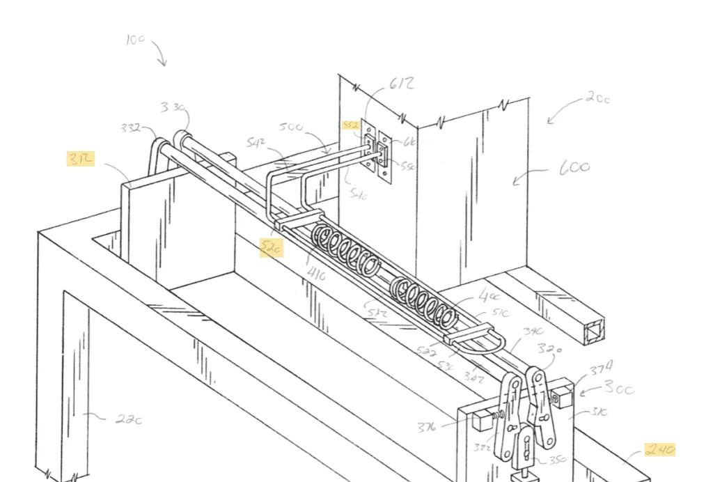
An apparatus for Induction hardening a spring having a helical or beehive shape. The apparatus has a rotation support system and an induction heating system. The rotation support system is designed to support the spring while the spring is heated by the induction heating system. The induction heating system has an induction coil system having a coil system. The coil system has a spaced region designed to receive the spring and to heat the spring while the spring is supported on the rotation support system.
 Coil springs or leaf springs are made by thermal deformation of steel profiles. Because of the characteristics of spring steel, there are certain requirements for heating temperature and time during the heating process. Except the preheating before rolling into spring coils or forging press into leaf springs, there are also other requests of different heat treatment, such as spring rod wire annealing, and steel panel induction surface hardening. Having the characteristics of rapid heating, fast shut down, accurate power output control, and varies frequency ranges, HLQ's induction heating power supply is very suitable for thermal deformation heating of spring steel, especially in the auto parts industry involving leaf springs or load-bearing spring manufacturing plants. Designed by the professionals at HLQ, our induction heating devices are all well-equipped with the advantages of energy-saving, fast start/stop, 24 hours duty cycle time, high power-point, high automation, high efficiency, easy maintenance, and long use life. Our induction heaters have been widely recognized by customers in the spring steel production industry.
 Coil springs or leaf springs are made by thermal deformation of steel profiles. Because of the characteristics of spring steel, there are certain requirements for heating temperature and time during the heating process. Except the preheating before rolling into spring coils or forging press into leaf springs, there are also other requests of different heat treatment, such as spring rod wire annealing, and steel panel induction surface hardening. Having the characteristics of rapid heating, fast shut down, accurate power output control, and varies frequency ranges, HLQ's induction heating power supply is very suitable for thermal deformation heating of spring steel, especially in the auto parts industry involving leaf springs or load-bearing spring manufacturing plants. Designed by the professionals at HLQ, our induction heating devices are all well-equipped with the advantages of energy-saving, fast start/stop, 24 hours duty cycle time, high power-point, high automation, high efficiency, easy maintenance, and long use life. Our induction heaters have been widely recognized by customers in the spring steel production industry.
The metal induction hardening process is a standard process used in spring fabrication. One common hardening process consists of a traditional atmospheric furnace. Such hardening processes are very slow. Springs can be formed from a variety of metals (e.g., stainless steel, carbon steel, alloy steel, etc.). When the metal of the spring is properly hardened and tempered, specific metallurgical parameters such as hardness and micro-structure can be attained.
When a spring is hardened by a traditional atmospheric furnace, the spring is first placed in an oven set at a certain temperature for a particular period of time. Thereafter, the spring is removed and quenched in oil or some other quenching liquid. After this initial hardening process, the spring hardness is generally higher than desired. As such, the spring is generally subjected to a tempering process until the spring obtains the desired physical properties. When the spring is properly processed, some of the crystalline structure of the steel is changed to tempered martensite with much of the carbides dissolved so as to provide the desired core structure of the spring and desired surface hardness of the spring.
Another process that is used for hardening springs is induction heating. The induction heating process occurs by inducing an electromagnetic field in a conductive material of the spring. Eddy currents are generated within the conductive material whose resistance leads to Joule heating. Induction heating can be used to heat steel to its melting point if need be which is more than sufficient to austenitize the product.
The induction heating process can provide a faster heating cycle time than heating by traditional atmospheric furnaces, and the induction heating process can simplify the material handling of the springs, and can potentially enable automation of the material handling of the spring in the hardening process. Although induction heating has several advantages over traditional atmospheric furnaces, induction heating of springs has problems with evenly heating the spring throughout spring length, overheating the ends of the spring, and the maintaining of induction heating coil efficiency.
2022年1月29日星期六
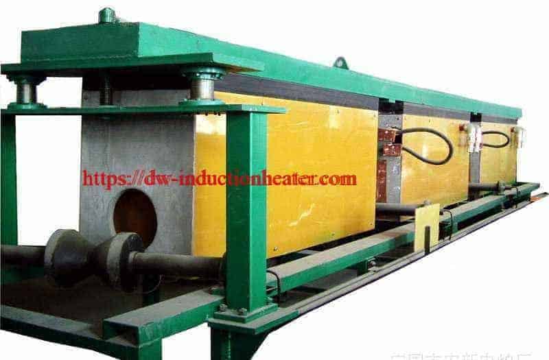
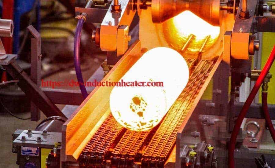
Billet Heating Furnace with Induction Heating
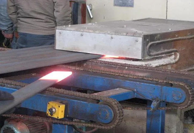
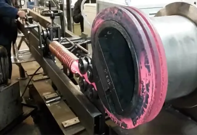
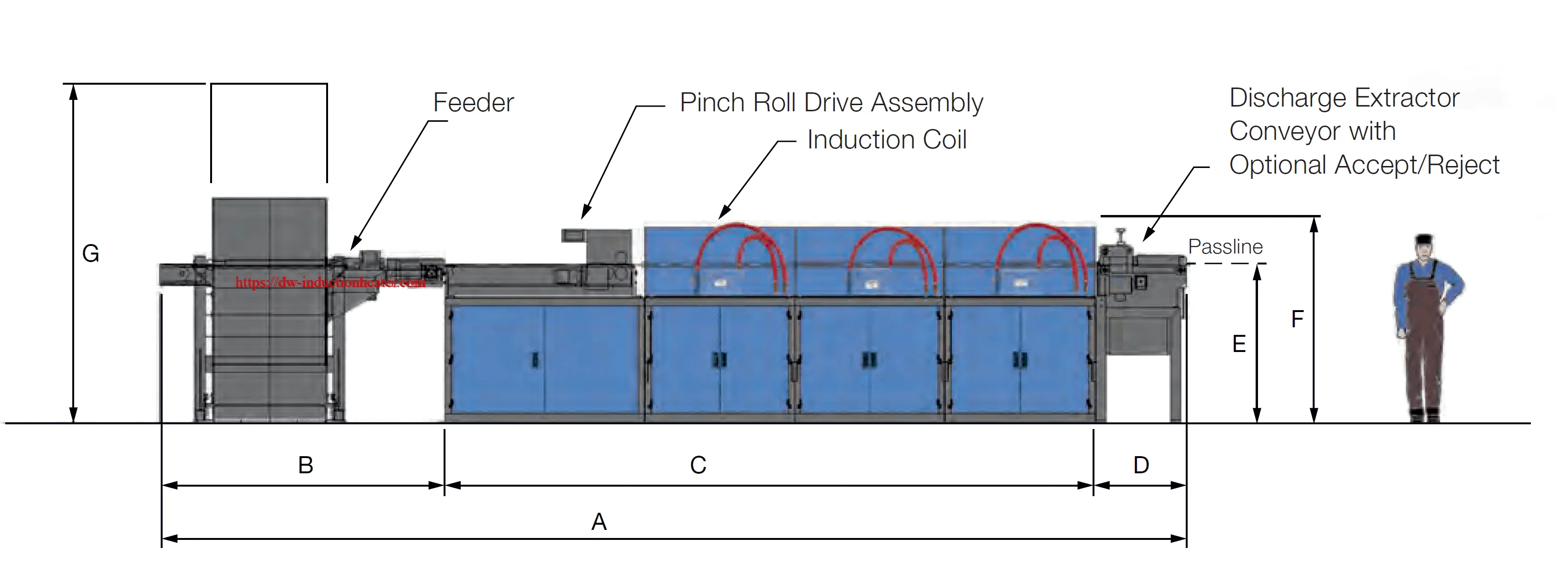
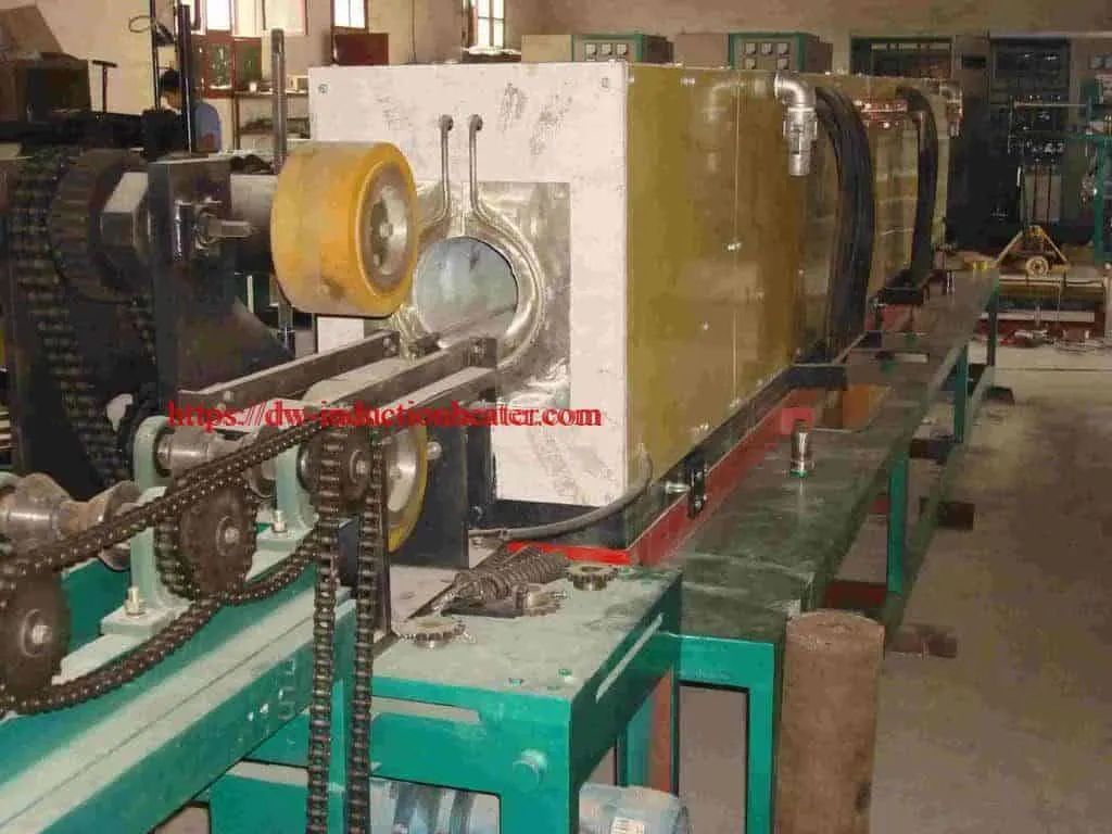
24h Continous Billet Heating Furnace with induction for the heating of copper/aluminum/iron steel billets before hot forming
 Product Description
For heating various of bar materials: such as steel & iron, bronze, brass, aluminum alloy, etc.
Picture just for reference, color is changable with different power.
Functions and special specifications customized by customer's requirements.
Features and Advantages:
1.Automatic:Automatic feeding, automatic selection of the work-piece is good or bad, automatic measurement of temperature, automatic discharge.
2. Integrated design: Save installation time,cost and space.
3. Operation panel embedded displays machine operating states, to facilitate fault diagnosis.
Product Description
For heating various of bar materials: such as steel & iron, bronze, brass, aluminum alloy, etc.
Picture just for reference, color is changable with different power.
Functions and special specifications customized by customer's requirements.
Features and Advantages:
1.Automatic:Automatic feeding, automatic selection of the work-piece is good or bad, automatic measurement of temperature, automatic discharge.
2. Integrated design: Save installation time,cost and space.
3. Operation panel embedded displays machine operating states, to facilitate fault diagnosis.
| Features | Detail | |
| 1 | Heating fast and stable | saving 20%- 30% electric energy than traditional way; High efficiency and low energy consumption |
| 2 | Small in size | Easy to install, operate and repair |
| 3 | Safe and reliable | No high voltage, very safe to your workers. |
| 4 | A cooling circulation system | Able to operate continuously 24 hours |
| 5 | complete self-protect function | many types of alarm lamps: over-current, over-voltage, over hot, water shortage etc. These lamps can control and protect machine. |
| 6 | Environmental protection | Almost no oxide layer, produced no exhaust, no waste-water |
| 7 | IGBT Type | Avoid the interruption of unrelated electric net; Ensure the long-life of the machine. |
| DW-MF-200 | DW-MF-250 | DW-MF-300 | DW-MF-400 | DW-MF-500 | DW-MF-600 | ||
| Input Voltage | 3phases, 380V/410V/440V , 50/60Hz | ||||||
| Max Input Current | 320A | 400A | 480A | 640A | 800A | 960A | |
| Oscillating frequency | 0.5KHz^20KHz ( Oscillating frequency will be customized according to the size of heating parts) | ||||||
| Duty Cycle Loading | 100%,24h continuously work | ||||||
| Cooling Water Desires | 0.1MPa | ||||||
| Dimension | Host | 1000X800X1500mm | 1500X800X2800mm | 850X1700X1900mm | |||
| Extension | extension will be customized according to the material and size of heating parts | ||||||
| Weight | 110kg | 150kg | 160kg | 170kg | 200kg | 220kg | |
| Depend on the dimension of extension | |||||||

Brazing stainless steel with induction
High frequency induction brazing stainless steel tube to stainless steel fitting with DW-HF-25kw-A induction heater.
Objective Brazing stainless steel tubing and stainless steel fittings Equipment DW-HF-25kw-A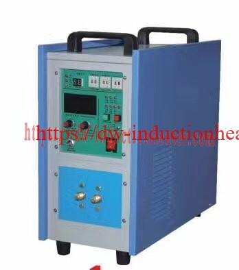 induction brazing machine
Materials
1.75″(44.45mm) Hexagon fitting
Power: 10.52 kW
Temperature: 1300°F (704°C)
Time: 30 seconds
Results and Conclusions:
- Induction heating pinpoints the heat to the desired area of the part
- Improved process control for precise heating to a desired temperature
- Power on demand and rapid, consistent heat cycles
- Technology without pollution, which is both clean and safe
Induction Heating Magnetic Iron Oxide
Induction Heating Magnetic Iron Oxide in water for hyperthermia application
Objective Heating magnetic iron oxide (Fe2O3) in water for hyperthermia application to determine the curve of temperature vs. time during induction heating
Material Magnetic iron oxide in water (magnetic field is 50-200kHz, 30kA/m), glass vial
Temperature Varies
Frequency 344 kHz
Equipment • DW-UHF-4.5kW induction heating system, equipped with a remote workhead containing two 0.33μF capacitors for a total of 0.66 μF
• An induction heating coil designed and developed specifically for this application.
Process A two turn helical coil is used to heat the glass vial. The temperature vs. time results are:
• 66º - 107 ºF (19º - 42 ºC) in 10 seconds
• 66º - 145 ºF (19º - 63 ºC) in 20 seconds
• 66º - 170 ºF (19º - 77 ºC) in 30 seconds
Results/Benefits Induction heating provides:
• Rapid & localized heating
• Uniform controllable heat
• Small bench top footprint
• Even distribution of heating

2022年1月28日星期五
Induction Soldering Cable to Metallic Plate
Objective
The purpose of this test is to demonstrate the induction soldering cable to metallic plate process.
Recommended Equipment
The recommended equipment for this test is the DW-UHF-6kw-I handheld induction heater.

 Key Parameters
Power: Up to 0.72 kW
Temperature: 482°F (250°C)
Time: 4.5 seconds to 14 seconds
Key Parameters
Power: Up to 0.72 kW
Temperature: 482°F (250°C)
Time: 4.5 seconds to 14 seconds
Results and Conclusions:
The results were satisfactory at 14 seconds. The complete process can be achieved in less than 5 seconds by increasing the frequency from under 200 kHz to over 300 kHz, as well as by increasing the induction heating power


Induction Soldering Wire of Co-axial
Induction Soldering Wire of Co-axial With High Frequency Heating Units
Objective To solder center-conductor and shielding braid of wire assemblies to 500 (250) °F(°C).
Material • Customer-supplied assemblies
• Temperature indicating paint
• Flux-cored solder wire
Temperature 500 (250) °F (°C)
Frequency 272 kHz
Equipment DW-UHF-4.5kW induction heating system, equipped with a remote heat station containing two 0.33 μF capacitors. An induction heating coil designed and developed specifically for this application.
Process A multi-turn helical coil is used and temperature-indicating paint is applied to the joint area. The wire assembly is placed over the induction heating coil, and RF power is applied. The time-to-temperature and the heating pattern on the part are established. The next wire assembly is placed on the coil, the assembly is heated and solder wire is fed into the joint. The assembly heats well and reaches 500 °F in 10 seconds.
Results/Benefits • elimination of a crimp process
• more reliable connections are made
• faster process times
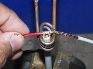


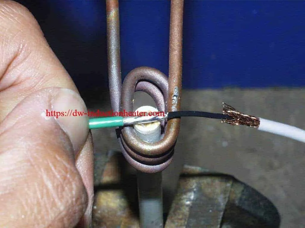
induction soldering fiber optic cable
Induction soldering fiber optic cable with high frequency induction heating units
Objective To heat a gold-plated ferrule and fiber optic cable to 475°F within 8 seconds for a soldering application
Material Gold-plated ferrule tube, fiber optic cable, solder preform
Temperature 475 ºF
Frequency 270 kHz
Equipment DW-UHF-4.5kW power supply with a specially designed induction coil.
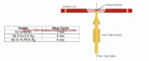
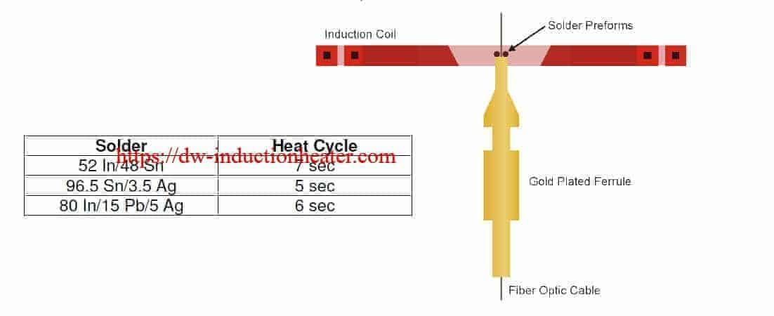
Process A specially designed, two-turn plate concentrator coil was used to provide uniform heat to the fiber optic assembly. The assembly was placed in a specially designed fixture, then placed inside the induction coil. RF power was applied until the solder flowed and created a solid joint.
Results Consistent and repeatable results were achieved using the DW-UHF-4.5kW power supply and induction coil with a 5 to 7 second heat cycle, depending on the type of solder used (see solder chart below).
2022年1月27日星期四
Induction Soldering Fuse Caps
Induction Soldering Fuse Caps With IGBT Induction Heating Units
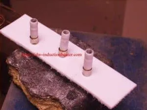
Objective Soldering three fuse caps simultaneously to reflow lead free solder and make a joint between the fuse cap and fuse wire guide
Material Plated copper end caps 0.375” (9.5mm) OD x 0.375” (9.5mm) height, ceramic fuse tube 1.5” tall (38.1mm) , lead free solder preforms
Temperature 700 ºF (371 ºC)
Frequency 286 kHz
Equipment • DW-UHF-20 kW induction heating system, equipped with a remote workhead containing two 1.0μF capacitors for a total of 0.5μF
• An induction heating coil designed and developed specifically for this application.
Process A three position two turn helical coil is used to solder three fuse caps simultaneously. The fuse assemblies are placed in the coil and the heat is applied in three cycles at 3.5 seconds per cycle to reflow the solder. On the production line the bottom caps are soldered first. The fuses are filled with sand and without flipping the assembly the top cap is soldered.
Results/Benefits Induction heating provides:
• Consistent, repeatable results
• Precise & accurate heat application
• Hands-free heating that involves no operator skill for manufacturing
• Even distribution of heating

Brazing Aluminum to Copper Tubes with Induction
Brazing Aluminum to Copper Tubes with Induction
Objective: To heat an aluminum manifold to 1050 ºF (566 ºC) for a brazing application:
Material :
- Cu tubes (3/4"/19mm)
- Cu tubes (5/8"/15.8mm)
- AI tubes (3/8"/9.5mm)
- AI manifold (5/8"/15.8mm)
- AI manifold (3/4"/19mm)
- Lucas-Milhaupt Handy One alloy 30-832
- Braze wire
- A two-turn oval helical induction heating coil designed and developed specifically for the aluminum assembly
- A five-turn helical induction heating coil designed and developed specifically for brazing the Cu tubes to AI joint assembly
- The client wanted more precise and repeatable heating than a torch could deliver, which induction was able to achieve .
- Temperature control: Induction allows for superior temperature control when compared to other methods, including a torch, which the client desired
Induction Brazing Carbide Onto Steel Part
Induction Brazing Carbide Onto Steel Part
 Objective
Brazing carbide onto steel workpiece
Equipment
DW-UHF-6KW-III Handheld Induction Brazing Heater
Objective
Brazing carbide onto steel workpiece
Equipment
DW-UHF-6KW-III Handheld Induction Brazing Heater
 Key Parameters
Power: 4kW
Temperature: Approximately 1500°F (815°C)
Time: 16 sec
Materials
Coil-
2 helical turns (20 mm ID)
1 planar turn (40 mm OD, 13 mm Height)
Carbide-
13 mm OD, 3 mm wall thickness
Steel piece–
20 mm OD, 13 mm ID
Key Parameters
Power: 4kW
Temperature: Approximately 1500°F (815°C)
Time: 16 sec
Materials
Coil-
2 helical turns (20 mm ID)
1 planar turn (40 mm OD, 13 mm Height)
Carbide-
13 mm OD, 3 mm wall thickness
Steel piece–
20 mm OD, 13 mm ID
Process:
- To demonstrate elimination of “hand feeding” the alloy, we formed the alloy into a ring to tightly fit over the center post tube. This method provides a uniform amount for each cycle, resulting in uniform joints and wetting.
- The custom made coil was then placed over the steel piece, where is was set for 14 seconds to heat the alloy.
- The alloy was heated at approximately 1500°F (815)°C
- The whole piece is left alone and cooled with ambient air
Results/Benefits:
- Brazing was successful all in under 20 seconds with 3kW
- High quality and repeatability of the brazed joints
- Increased productivity
- Rings will need to be developed for specific joints to prevent the use of too much alloy
- Precise control of the time and temperature


2022年1月26日星期三
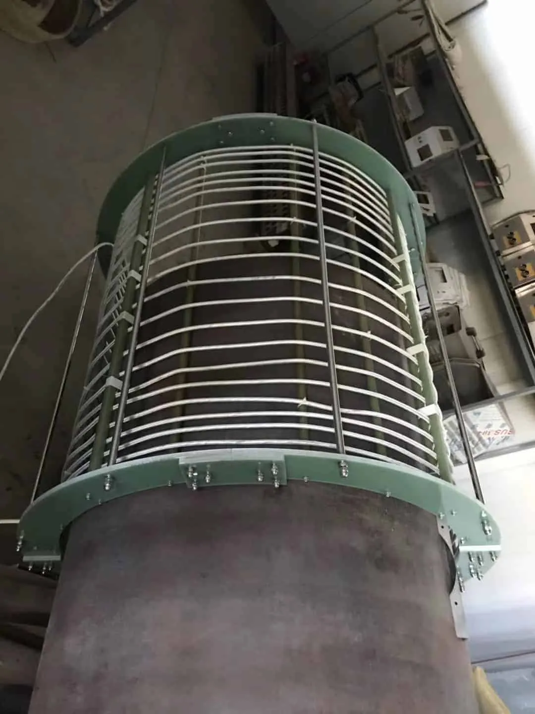
Induction Drying Grain with Induction Heating method
Energy savings at the induction drying grain with induction heating method
Annually Kazakhstan produces around 17-19 million tons of grain in clean weight,exports about 5 million tons of grain, and the average volume of domestic consumption reaches 9-11 million tons. Further development of the grain industry and promotion of grain export requires developing the infrastructure of storage, transportation and drying of grain, including the construction of new and reconstruction of the old grain silos, construction of port terminals and purchase of dry cargo vessels and grain carriers (Baum, 1983). There is a need to modernize the industry and the task requires a intensive efforts of the state and national grain producers. Participants of Astana Kazakh Grain Forum V KAZGRAIN-2012 discussed the current state of grain market, trends and price expectations, as well as challenging issues in logistics and infrastructure. It was noted that 10 years ago Kazakhstan could not be considered as a grain exporter, while in current time the export issues are recognized as priority ones. And the production and drying of grain takes one of the leading places both in agroindustrial complex, and the economy as a whole. Analysis of experience of many manufacturing enterprises in post-harvest grain processing proves that the primary task in ensuring the safety and quality of newly harvested seeds is their drying. Importance of grain drying increases in the humid zone: delay in drying or carrying out this operation with violation of technological regimes inevitably cause crop losses. According to the researches in 25-28% humidity of heap for three days the germination decreases by 20%. And the losses of dry matter makes 0.7-1% per day when a moisture of the grain heap is 37% (Ginzburg, 1973).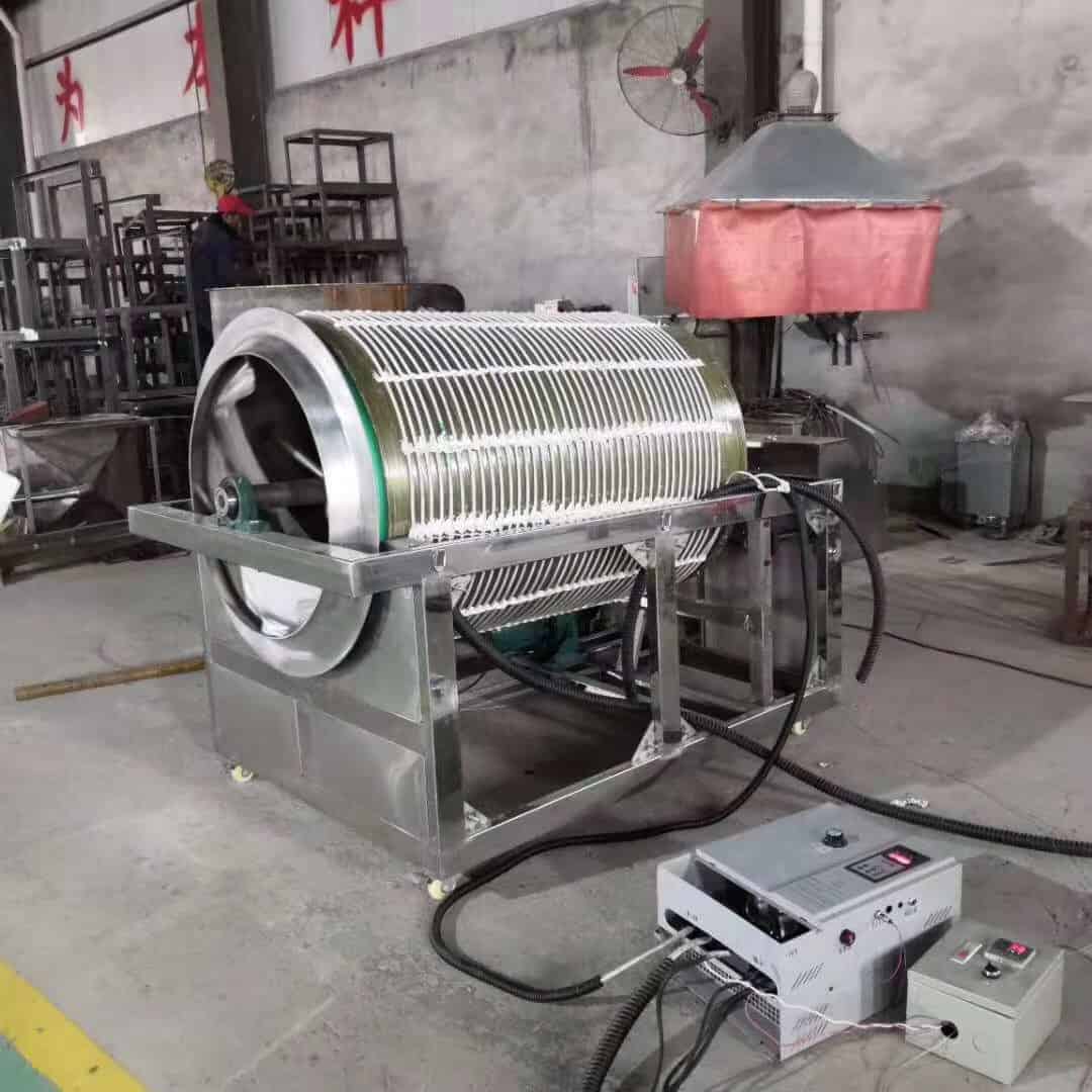 The important factors in efficient use of dryers in agriculture are provision of higher grain quality, increase of bandwidth of units, as well as lowering energy costs. Base for improving the effectiveness of existing dryers in agriculture is ensuring sufficient and stable removal of moisture from one cubic meter in cameras of grain dryers. One of the reason preventing for this is that the cooling units, built into the drying shaft, do not create optimal conditions for full grain cooling and thereby reduce the effective volume of the drying shaft and moisture removal from a cubic meter of the camera.
Since the 2010 production of wheat demonstrates a stable growth trend: crop area has increased by 17%, yield has increased by 25%, and total yield - by 52%. In the 1th January in 2012 Kazakhstan had 258 silos with a storage capacity 14 771.3 thousand tons and elevators with storage capacity 14 127.8 thousand tons. Increase of yield and gross harvest requires improving drying technology to avoid crop losses and maintain grain quality.
The most perspective method for grain drying and removing moisture is the induction heating method which remains little studied and rarely used in practice due to considerable imperfections in technologies of frequency convertors manufacturing. Though the induction heating equipment production is currently developing and use of it grain drying practice becomes more preferable compared to traditional heating methods (Zhidko, 1982).
At present time induction heating is used for surface hardening of steel products, through heating for plastic deformation (forging, stamping, pressing, etc.), metal melting, heat treatment (annealing, tempering, normalizing, quenching), welding, welding, soldering, metals. Indirect induction heating is used for heating of technological equipment (pipelines, tanks, etc.), heating of liquids, drying of coats and materials (e.g., wood). The most important parameter of induction heating installations is frequency. For each process (surface hardening, through heating) there is an optimal frequency range, providing the best technological and economic performance. Frequencies from 50Hz to 5 MHz are used for induction heating.
Advantages of induction heating include the following:
The important factors in efficient use of dryers in agriculture are provision of higher grain quality, increase of bandwidth of units, as well as lowering energy costs. Base for improving the effectiveness of existing dryers in agriculture is ensuring sufficient and stable removal of moisture from one cubic meter in cameras of grain dryers. One of the reason preventing for this is that the cooling units, built into the drying shaft, do not create optimal conditions for full grain cooling and thereby reduce the effective volume of the drying shaft and moisture removal from a cubic meter of the camera.
Since the 2010 production of wheat demonstrates a stable growth trend: crop area has increased by 17%, yield has increased by 25%, and total yield - by 52%. In the 1th January in 2012 Kazakhstan had 258 silos with a storage capacity 14 771.3 thousand tons and elevators with storage capacity 14 127.8 thousand tons. Increase of yield and gross harvest requires improving drying technology to avoid crop losses and maintain grain quality.
The most perspective method for grain drying and removing moisture is the induction heating method which remains little studied and rarely used in practice due to considerable imperfections in technologies of frequency convertors manufacturing. Though the induction heating equipment production is currently developing and use of it grain drying practice becomes more preferable compared to traditional heating methods (Zhidko, 1982).
At present time induction heating is used for surface hardening of steel products, through heating for plastic deformation (forging, stamping, pressing, etc.), metal melting, heat treatment (annealing, tempering, normalizing, quenching), welding, welding, soldering, metals. Indirect induction heating is used for heating of technological equipment (pipelines, tanks, etc.), heating of liquids, drying of coats and materials (e.g., wood). The most important parameter of induction heating installations is frequency. For each process (surface hardening, through heating) there is an optimal frequency range, providing the best technological and economic performance. Frequencies from 50Hz to 5 MHz are used for induction heating.
Advantages of induction heating include the following:
- Transmission of electrical energy directly into the heating body allows implementing direct heating of materials, thereby the heating rate is
- Transmission of electrical energy directly into the heating body does not require contact devices. This is useful for automated line
- When a heating material is a dielectric, e.g. grain, then the power is evenly distributed throughout volume of the heating material. Consequently, this induction method provides fast heating of
- Induction heating in most cases can increase productivity and improve working conditions. Induction device can be regarded as a kind of transformer, when the primary winding (inductor) is connected to the AC power source, and the heating material serves as the secondary
 Reduction of cost of the entire installation requires development and implementation of simple in design induction heaters.
The main difference between induction heating from traditional methods of drying lies in volumetric heating. The heat penetrates into the product (material) not from the surface; it is formed in the whole volume at once, this process allows drying grain effectively with low energy consumption. Even distribution of moisture occurs in a dried material during the heating induction process. Induction does not assume heat transfer from heater to a material. While using other methods of drying requires heating the air, then transfer the heat from the hot air to material. At each stage - air heating, its transportation, and heat transfer to products - the heat losses are unavoidable.
Nowadays enterprises in Kazakhstan practically do not use induction heaters as they are very expensive. Old lamp models of induction heating machines are outdated and they are not manufactured.
Reduction of cost of the entire installation requires development and implementation of simple in design induction heaters.
The main difference between induction heating from traditional methods of drying lies in volumetric heating. The heat penetrates into the product (material) not from the surface; it is formed in the whole volume at once, this process allows drying grain effectively with low energy consumption. Even distribution of moisture occurs in a dried material during the heating induction process. Induction does not assume heat transfer from heater to a material. While using other methods of drying requires heating the air, then transfer the heat from the hot air to material. At each stage - air heating, its transportation, and heat transfer to products - the heat losses are unavoidable.
Nowadays enterprises in Kazakhstan practically do not use induction heaters as they are very expensive. Old lamp models of induction heating machines are outdated and they are not manufactured.
Grain drying by induction heating. Drying in the falling layer
We suggest the induction heating method of grain drying (Figure 1) where the grain material passes, driven by gravity power, through the drying shaft. At the top of the dryer grain is loaded by bucket conveyors or other transport devices; then grain gets into drying tower. In the camera of drying tower the inductor, connected to frequency converter, creates electromagnetic field (flux) of high frequency.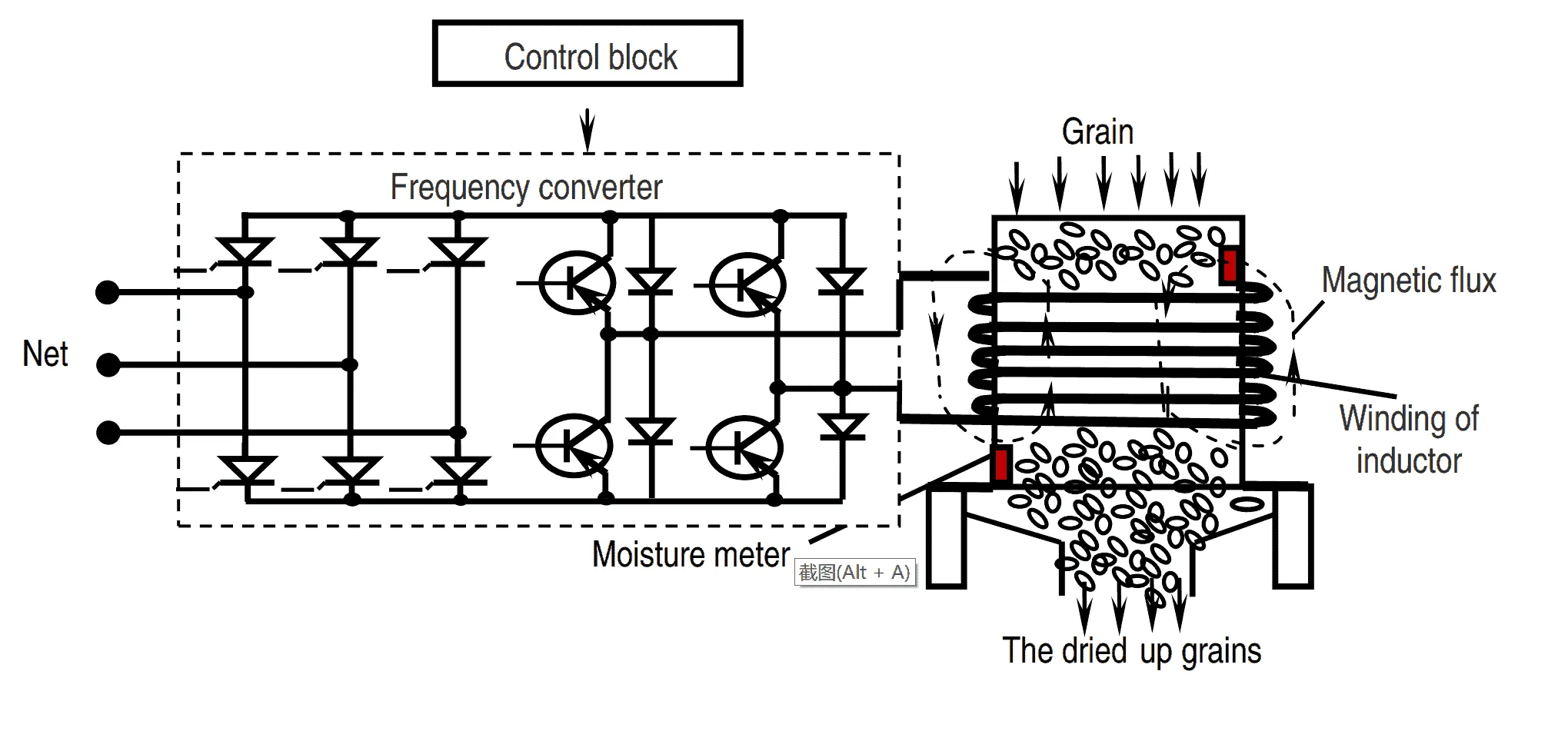 Drying in falling layer. Falling layer represents highly discharged gravitational moving grain stream, partially offset by upward flow of gas (aerodynamic braking). The true concentration of grain increases in the course of the movement. Drying in suspended layer. The suspended state of grain is achieved in the raising stream of gas when increasing speed of power supply. In the process the whole surface of grain is involved to heat and moisture exchange with the gas. The time of stay of grain in the pneumo tube does not exceed few seconds; temperature of drying agent makes 350-400 °C. However, the reduction of moisture amounts to a fraction percent. Therefore, the apparatus with weighted layers of grain are used not as separate dryer, but as an element of multi-chamber combined dryer.
Conclusion
Today agricultural firms and elevators are equipped mostly by the direct flow shaft dryers. These dryers suggest considerable unevenness in heating and drying of grain, which in turn causes substantial thermal drying costs. The main reason here is the imperfection in supplying the drying agent and atmospheric air to dehydrating layers of grain.
An important condition for quality work of grain dryers is an efficient cooling of dried grain. According to plan the cooling devices of grain dryers are designed so that the temperature of the grain at the output should not exceed the atmospheric air temperature by more than 10°C. However, in practice this value reaches more than 12°C when the air temperature is higher than 15°C. Also modern grain dryers provide considerable unevenness in cooling of the individual layers of grain. In the discussed context applying of induction heating drying can be the more suitable way in terms of productivity, quality and cost efficiency.
References
Baum, A., 1983. Grain drying [in Russian], Moscow: Kolos
Ginzburg, A., 1973. Essentials of theory and technology in drying of foodstuffs [in Russian], Moscow: Food industry
Zhidko, V., 1982. Grain drying and grain dryers [in Russian], Moscow: Kolos
Drying in falling layer. Falling layer represents highly discharged gravitational moving grain stream, partially offset by upward flow of gas (aerodynamic braking). The true concentration of grain increases in the course of the movement. Drying in suspended layer. The suspended state of grain is achieved in the raising stream of gas when increasing speed of power supply. In the process the whole surface of grain is involved to heat and moisture exchange with the gas. The time of stay of grain in the pneumo tube does not exceed few seconds; temperature of drying agent makes 350-400 °C. However, the reduction of moisture amounts to a fraction percent. Therefore, the apparatus with weighted layers of grain are used not as separate dryer, but as an element of multi-chamber combined dryer.
Conclusion
Today agricultural firms and elevators are equipped mostly by the direct flow shaft dryers. These dryers suggest considerable unevenness in heating and drying of grain, which in turn causes substantial thermal drying costs. The main reason here is the imperfection in supplying the drying agent and atmospheric air to dehydrating layers of grain.
An important condition for quality work of grain dryers is an efficient cooling of dried grain. According to plan the cooling devices of grain dryers are designed so that the temperature of the grain at the output should not exceed the atmospheric air temperature by more than 10°C. However, in practice this value reaches more than 12°C when the air temperature is higher than 15°C. Also modern grain dryers provide considerable unevenness in cooling of the individual layers of grain. In the discussed context applying of induction heating drying can be the more suitable way in terms of productivity, quality and cost efficiency.
References
Baum, A., 1983. Grain drying [in Russian], Moscow: Kolos
Ginzburg, A., 1973. Essentials of theory and technology in drying of foodstuffs [in Russian], Moscow: Food industry
Zhidko, V., 1982. Grain drying and grain dryers [in Russian], Moscow: Kolos
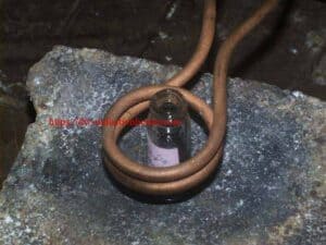
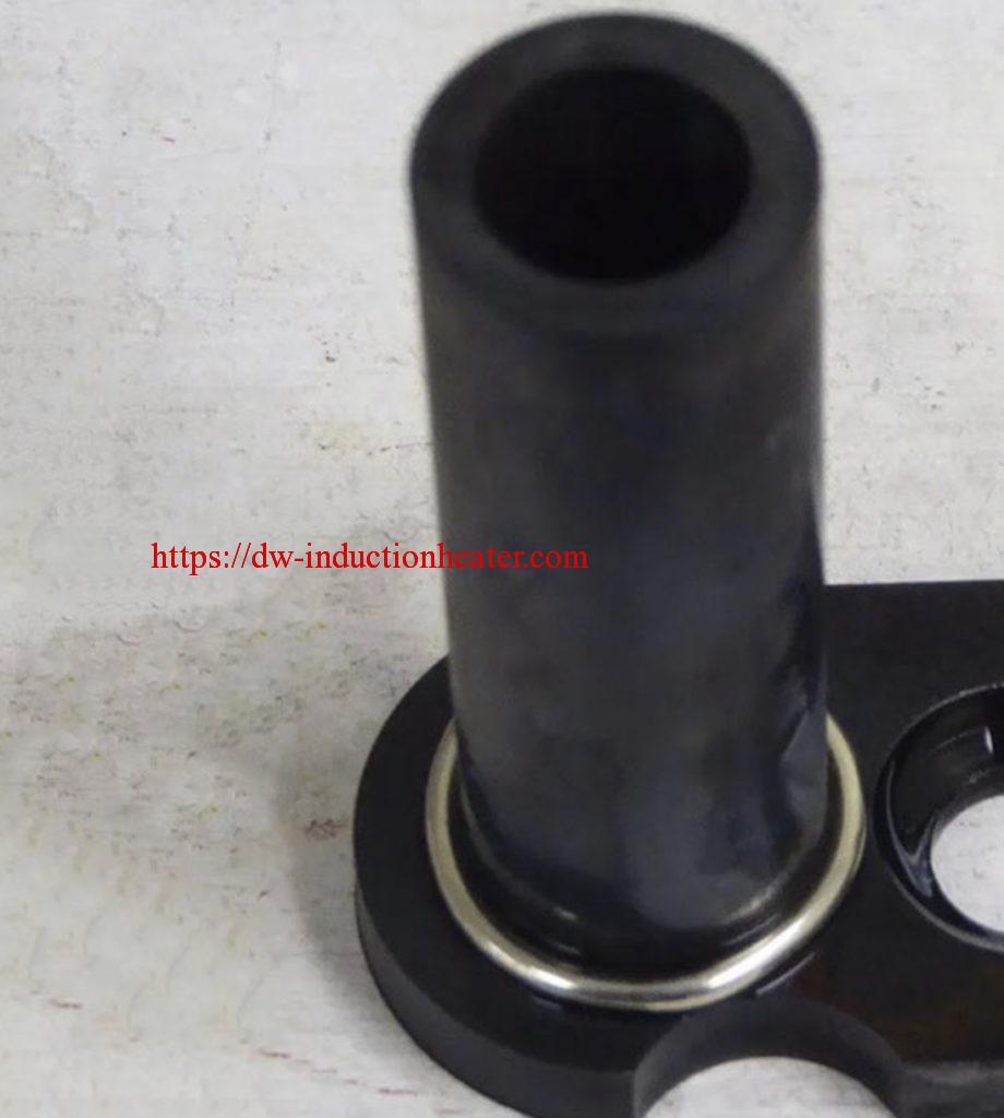
Induction Brazing Steel Tube
Induction Brazing Steel Tube
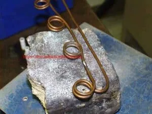
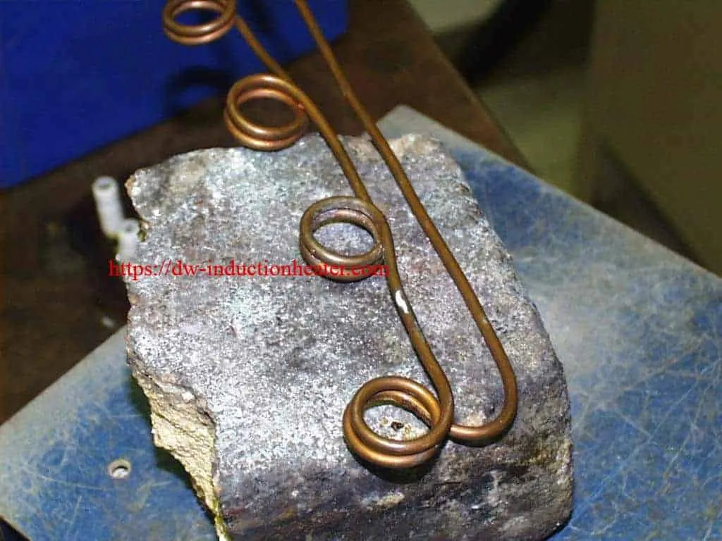
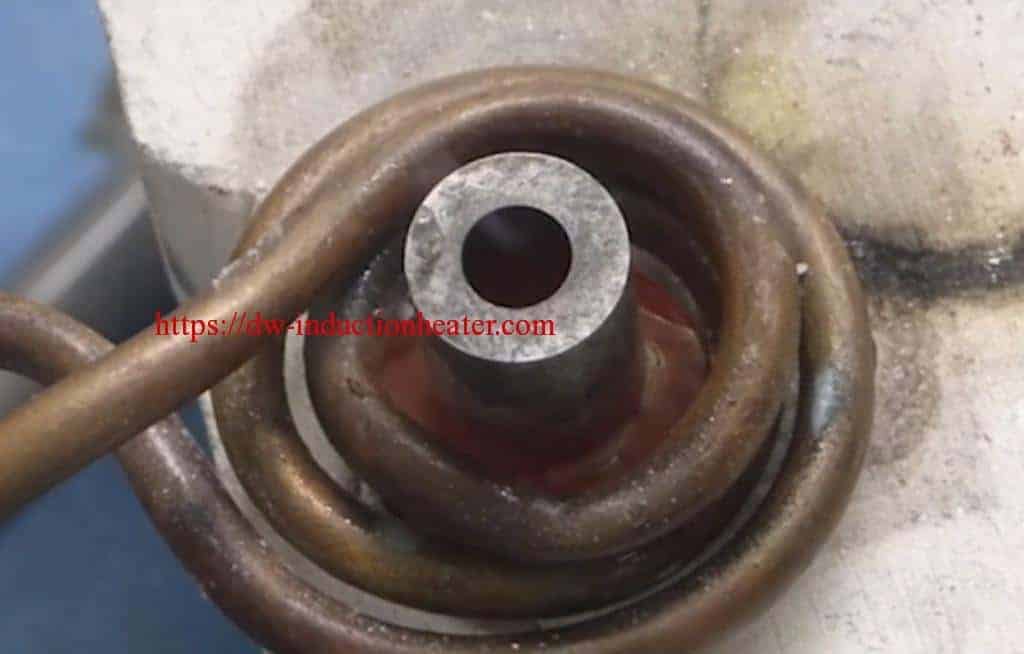
Objective: To heat an oil suction assembly (steel tubing and filter cap) to 1,850°F (1010°C) within 15 seconds for a brazing application.
Material 0.125" (3.2mm) diameter steel tube and filter cap assembly, high temperature brazing flux, copper ring.
Temperature 1850°F(1010°C)
Frequency 500 kHz
Equipment • DW-UHF-6KW-I induction heating system equipped with a remote workhead containing 0.66 μF capacitors • An induction heating coil designed and developed specifically for this application.
Process A two-turn, specially-contoured helical induction coil is used to heat the tube assembly near the joint area. A copper ring and high temperature flux are then applied to the joint area. Power is applied for 15 seconds until the braze flows.
Results/Benefits Induction heating provides:
• Easy loading and unloading of parts
• Heat very precise areas within production tolerances
• Hands free heating that involves minimal operator skill for manufacturing
Induction Brazing Copper Pipe Fittings
Induction Brazing Copper Fittings
Objective: Copper 'tees' and 'ells' are to be brazed to the aluminum body of a refrigeration valve
Material: customer's valve copper fittings braze
Temperature: 2550 ºF (1400°C)
Frequency: 585 kHz
Equipment: DW-UHF-10kw induction heating system including a workhead containing two 1.5μF capacitors (total 0.75μF) and a three-turn helical coil
Process: The valve is placed inside the coil and RF induction heating power is applied until the part is heated to the required temperature and the braze is seen to flow into the joint. Two tube sizes were run using the same induction heating system settings with differing cycle times.
Results/Benefits • energy is applied only to the zone to be heated • heating of the joint/braze is uniform and repeatable
2022年1月25日星期二
High Frequency Welding
High Frequency Welding Machine Manufacturer/RF PVC welding machine for welding plastic,etc.
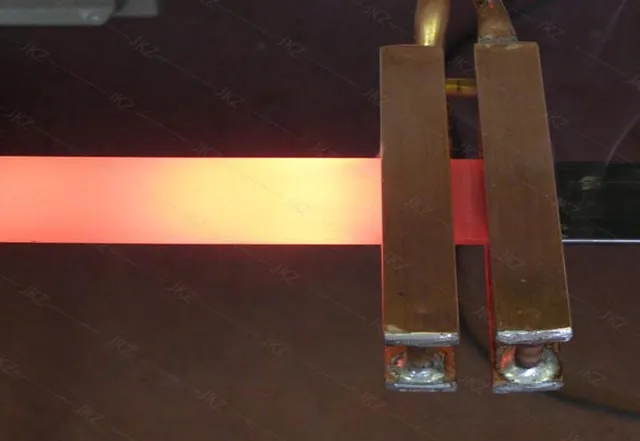
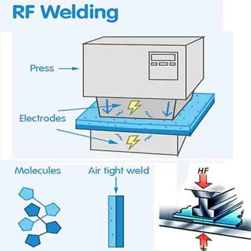
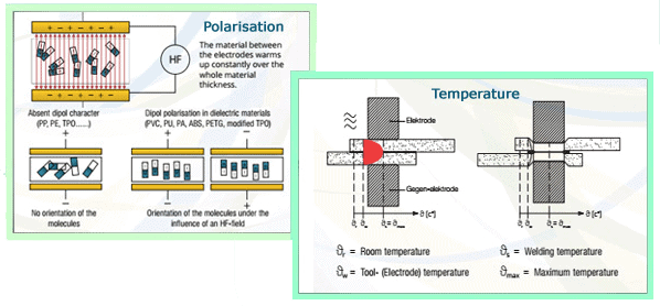
High Frequency Welding, known as Radio Frequency (RF) or Dielectric welding, is the process of fusing materials together by applying radio frequency energy to the area to be joined. The resulting weld can be as strong as the original materials. HF Welding relies on certain properties of the material being welded to cause the generation of heat in a rapidly alternating electric field. This means that only certain materials can be welded using this technique. The process involves subjecting the parts to be joined to a high frequency (most often 27.12MHz) electromagnetic field, which is normally applied between two metal bars. These bars also act as pressure applicators during heating and cooling. The dynamic electric field causes the molecules in polar thermoplastics to oscillate. Depending on their geometry and dipole moment, these molecules may translate some of this oscillatory motion into thermal energy and cause heating of the material. A measure of this interaction is the loss factor, which is temperature and frequency dependent.
Polyvinylchloride (PVC) and polyurethanes are the most common thermoplastics to be welded by the RF process. It is possible to RF weld other polymers including nylon, PET, PET-G, A-PET, EVA and some ABS resins, but special conditions are required, for example nylon and PET are weldable if preheated welding bars are used in addition to the RF power.
HF welding is generally not suitable for PTFE, polycarbonate, polystyrene, polyethylene or polypropylene. However, due to the impending restrictions in the use of PVC, a special grade of polyolefin has been developed which does have the capability to be HF welded.
The primary function of HF welding is to form a joint in two or more thicknesses of sheet material. A number of optional features exist. The welding tool can be engraved or profiled to give the entire welded area a decorative appearance or it can incorporate an embossing technique to place lettering, logos or decorative effects on the welded items. By incorporating a cutting edge adjacent to the welding surface, the process can simultaneously weld and cut a material. The cutting edge compresses the hot plastic sufficiently to allow the excess scrap material to be torn off, hence this process is often referred to as tear-seal welding.
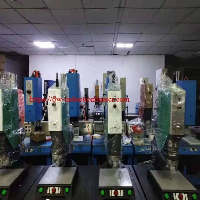
A typical plastic welder consists of a high frequency generator (which creates the radio frequency current), a pneumatic press, an electrode that transfers the radio frequency current to the material that is being welded and a welding bench that holds the material in place. The machine could also have a grounding bar that is often mounted behind the electrode, which leads the current back to the machine (grounding point). There are different types of plastic welders, the most common being tarpaulin machines, packaging machines and automated machines.
By regulating the machine’s tuning, the field strength can be adjusted to the material being welded. When welding, the machine is surrounded by a radio frequency field that, if too strong, can heat up the body somewhat. This is what the operator needs to be protected from. The strength of the radio frequency field also depends on the type of machine being used. Generally, machines with visible open electrodes (unshielded) have stronger fields than machines with enclosed electrodes.
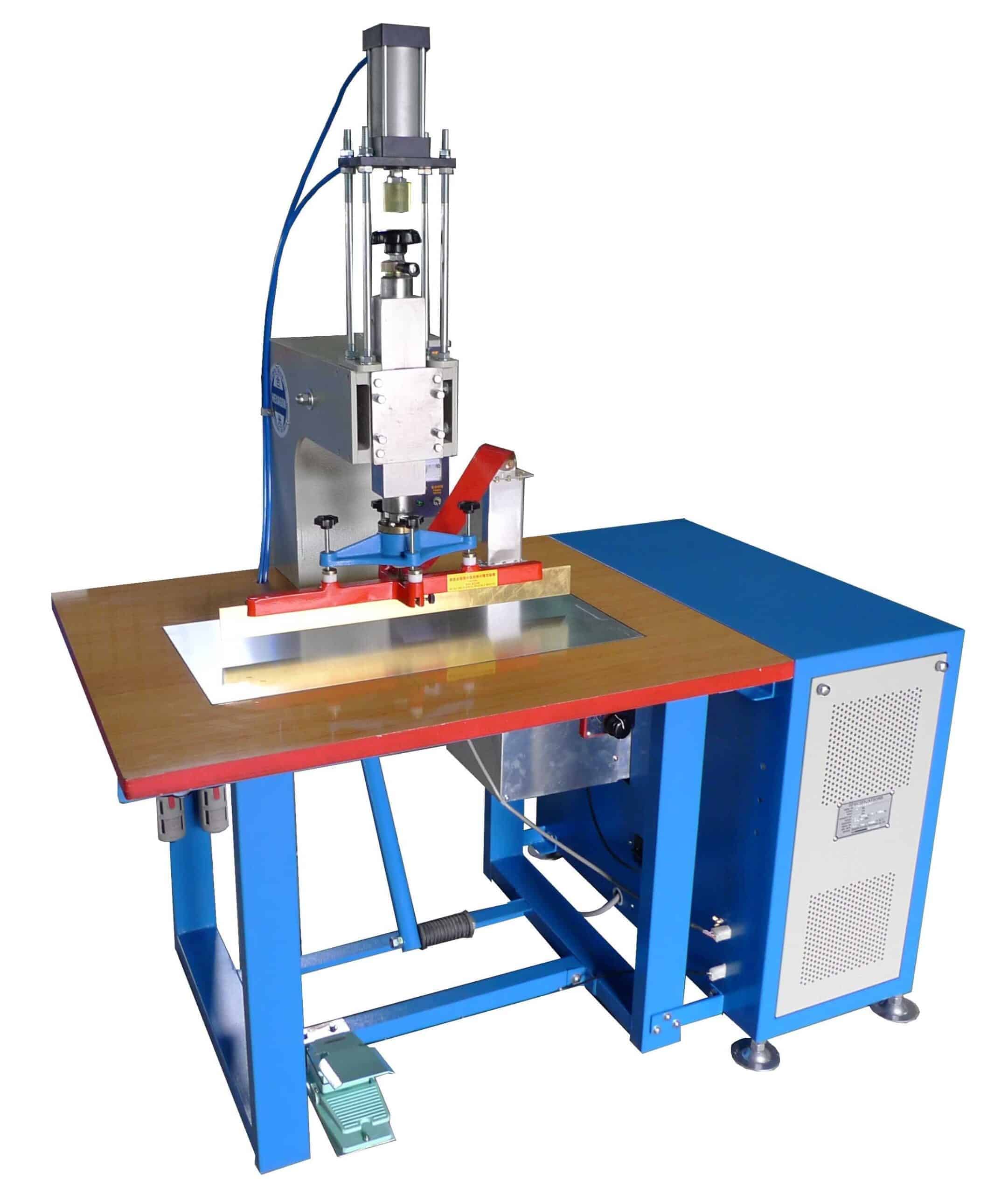 A typical plastic welder consists of a high frequency generator (which creates the radio frequency current), a pneumatic press, an electrode that transfers the radio frequency current to the material that is being welded and a welding bench that holds the material in place. The machine could also have a grounding bar that is often mounted behind the electrode, which leads the current back to the machine (grounding point). There are different types of plastic welders, the most common being tarpaulin machines, packaging machines and automated machines.
By regulating the machine’s tuning, the field strength can be adjusted to the material being welded. When welding, the machine is surrounded by a radio frequency field that, if too strong, can heat up the body somewhat. This is what the operator needs to be protected from. The strength of the radio frequency field also depends on the type of machine being used. Generally, machines with visible open electrodes (unshielded) have stronger fields than machines with enclosed electrodes.
A typical plastic welder consists of a high frequency generator (which creates the radio frequency current), a pneumatic press, an electrode that transfers the radio frequency current to the material that is being welded and a welding bench that holds the material in place. The machine could also have a grounding bar that is often mounted behind the electrode, which leads the current back to the machine (grounding point). There are different types of plastic welders, the most common being tarpaulin machines, packaging machines and automated machines.
By regulating the machine’s tuning, the field strength can be adjusted to the material being welded. When welding, the machine is surrounded by a radio frequency field that, if too strong, can heat up the body somewhat. This is what the operator needs to be protected from. The strength of the radio frequency field also depends on the type of machine being used. Generally, machines with visible open electrodes (unshielded) have stronger fields than machines with enclosed electrodes.
When describing radio frequency electromagnetic fields, the field’s frequency is often mentioned. The permitted frequencies for plastic welders are 13.56, 27.12, or 40.68 megahertz (MHz). The most popular industrial frequency for HF welding is 27.12MHz.
The radio frequency fields from a plastic welder spread out around the machine, but most often it is only right next to the machine that the field is so strong that precautions need to be taken. The field’s strength decreases sharply with distance from the source. The strength of the field is given in two different measurements: the electric field strength is measured in volts per metre (V/m), and the magnetic field strength is measured in amperes per metre (A/m). Both of these must be measured to get an idea of how strong the radio frequency field is. The current that goes through you if you touch the equipment (contact current) and the current that that goes through the body when welding (induced current) must also be measured.
Advantages of High Frequency Welding Technology
- HF sealing occurs from the inside out by using the material itself as a heat source. The heat is focused at the weld target so that the surrounding material does not have to be super-heated to arrive at a target temperature at the joint.
- With HF heating is generated only when the field is energized. Once the generator cycles, the heat is turned off. This allows for greater control over the amount of energy that the material sees over the entire cycle. In addition, HF-generated heat does not radiate off the die like on a heated die. This prevents heat-degredation of the material abutting the weld.
- HF tooling is usually run "cold". This means that once the HF is turned off, the material stops being heated, but remains under pressure. In this fashion it is possible to both instantly heat, weld, and cool the material under compression. More control over the weld results in more control over the resulting extrusion, thus increasing the weld strength.
- RF welds are "clean" because the only material needed to produce an HF weld is the material itself. There are no adhesives or by-products involved in HF
Induction Annealing Brass Bullet Shells
Induction Annealing Brass Bullet Shells Heating Treatment UHF Series With Induction Heating System
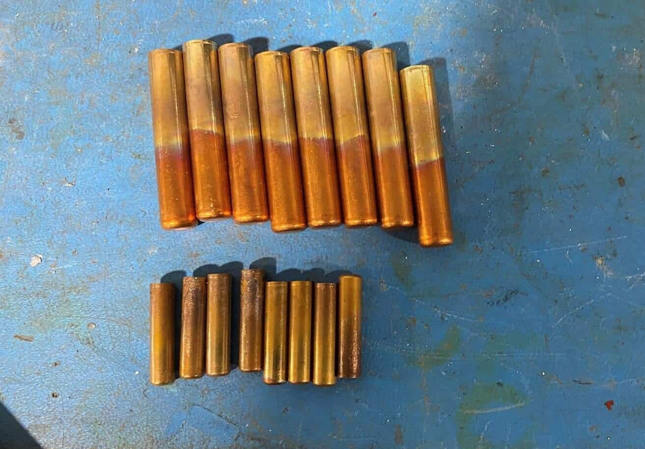
Application Note Objective: A manufacturer of brass bullet shells wants to upgrade their existing induction heating equipment and is looking for improved efficiency. The goal of this application test is to demonstrate that the DW-UHF-6KW-III induction system will meet and exceed its requirements for achieving improved heating times and maintaining heat uniformity within the targeted area. Two sizes of brass ammunition shells were used for the test – bullet casings with 1.682” (42.7 mm) length and 0.929” (23.5 mm) length. The targeted annealing time is 0.6 seconds for both parts using a single induction heating coil. Equipment:
HLQ DW-UHF-6kW-III air-cooled induction heating system was utilized in the annealing process. Tempilaq paint was used to determine if the desired temperature in the annealed area is reached.
Equipment:
HLQ DW-UHF-6kW-III air-cooled induction heating system was utilized in the annealing process. Tempilaq paint was used to determine if the desired temperature in the annealed area is reached.
Process:
The brass bullet shells were positioned in the induction heating coil. The area to be annealed took about 60% of the part’s length counting from the open end. The heated area was painted with Tempilaq which helped us evaluate the temperature distribution. Both parts successfully reached the target temperature of 750°F (398°C) in 0.6sec. For the smaller part, the power supply power was reduced to 45% to prevent the part’s overheating.
 Induction heating provides improved control of the annealing process. Repeatable heating profiles can easily be obtained by precise regulation of the heating power. Since the workpiece is directly heated by the magnetic field, a faster response can be achieved. Moreover, the high overall efficiency of the induction heating process is crucial for such lengthy treatment.
Compared to most of the standard methods, induction annealing is a clean and easy to automate, contactless approach providing a high quality of the treated workpieces.
Induction heating provides improved control of the annealing process. Repeatable heating profiles can easily be obtained by precise regulation of the heating power. Since the workpiece is directly heated by the magnetic field, a faster response can be achieved. Moreover, the high overall efficiency of the induction heating process is crucial for such lengthy treatment.
Compared to most of the standard methods, induction annealing is a clean and easy to automate, contactless approach providing a high quality of the treated workpieces.

Induction Annealing
In general, the main purpose of induction annealing heat treatment is to soften the steel, regenerate overheated steel structures or just remove internal tensions. It basically consists of heating to austenitizing temperature (800ºC and 950ºC depending on the type of steel), followed by slow cooling. Induction Annealing is a heat treatment process which involves heating of material above its recrystallization temperature. The aim is to reach and maintain a suitable temperature for enough time followed by proper cooling. It is often used in metallurgy and material science to make the treated sample more workable by reducing its hardness and increasing its ductility (ability to undergo a change of form without breaking). Annealing alters the physical and sometimes the chemical properties of the material as recrystallization is obtained during the process of cooling. Therefore, the outcoming structures of many alloys, including carbon steel, are both dependent on the heating and on the cooling rate. Ferrous metals, such as steel, require slow cooling to anneal. Other materials (e.g. copper, silver) can be either cooled slowly in air or quickly quenched in water.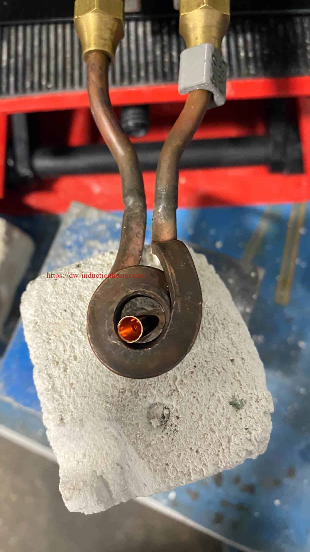 Induction heating provides improved control of the annealing process. Repeatable heating profiles can easily be obtained by precise regulation of the heating power. Since the workpiece is directly heated by the magnetic field, a faster response can be achieved. Moreover, the high overall efficiency of the induction heating process is crucial for such lengthy treatment.
Compared to most of the standard methods, induction annealing is a clean and easy to automate, contactless approach providing a high quality of the treated workpieces.
Induction heating provides improved control of the annealing process. Repeatable heating profiles can easily be obtained by precise regulation of the heating power. Since the workpiece is directly heated by the magnetic field, a faster response can be achieved. Moreover, the high overall efficiency of the induction heating process is crucial for such lengthy treatment.
Compared to most of the standard methods, induction annealing is a clean and easy to automate, contactless approach providing a high quality of the treated workpieces.
Induction annealing heating advantages:
- Processed in line with control of parameters in real time
- Metallurgical results similar to those obtained in conventional ovens
- Less environmental pollution
- Increase energy efficiency
- Reduced processing time
- Ability to control the heat, temperature accuracy
- Ability to heat small areas without changing the characteristics of the rest of the part
- Cycle accurate and repetitive heat
- Reduction of surface oxidation
- Improved job environment

订阅:
评论 (Atom)
我的简介

- HLQ induction heating machine
- HLQ induction heating machine manufacturer provides the service of induction brazing,melting,hot forming,hardening surface,annealing,shrink fitting,PWHT,etc.