显示标签为“Highfrequencysolderingwire”的博文。显示所有博文

2024年5月18日星期六

Induction Soldering Wire of Co-axial

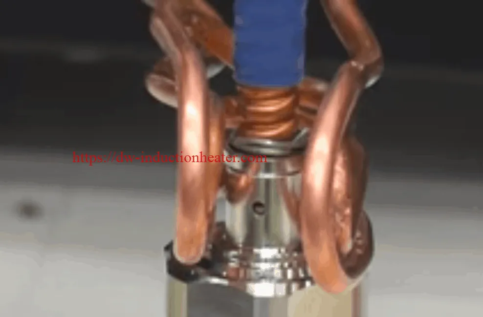
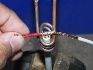
Induction Soldering Wire of Co-axial With High Frequency Heating Units Objective To solder center-conductor and shielding braid of wire assemblies to 500 (250) °F(°C). Material • Customer-supplied assemblies • Temperature indicating paint • Flux-cored solder wire Temperature 500 (250) °F (°C) Frequency 272 kHz Equipment DW-UHF-4.5kW induction heating system, equipped with a remote heat station containing two 0.33 μF capacitors. An induction heating coil designed and developed specifically for this application. Process A multi-turn helical coil is used and temperature-indicating paint is applied to the joint area. The wire assembly is placed over the induction heating coil, and RF power is applied. The time-to-temperature and the heating pattern on the part are established. The next wire assembly is placed on the coil, the assembly is heated and solder wire is fed into the joint. The assembly heats well and reaches 500 °F in 10 seconds. Results/Benefits • elimination of a crimp process • more reliable connections are made • faster process times induction soldering wire                 soldering wire together https://dw-inductionheater.com/induction-soldering-wire-of-co-axial.html?feed_id=246072&_unique_id=6648e1255c378
2024年4月1日星期一

Induction Soldering Copper Wire Connectors

Objective The objective of this application test is to determine heating times for induction soldering copper wire connectors onto a copper coaxial cable. The customer would like to replace hand soldering with soldering irons, with induction soldering. Hand soldering can be labor intensive, and the resulting solder joint is highly dependent on the skill of the operator. Induction soldering allows finite process control, and provides a consistent result.
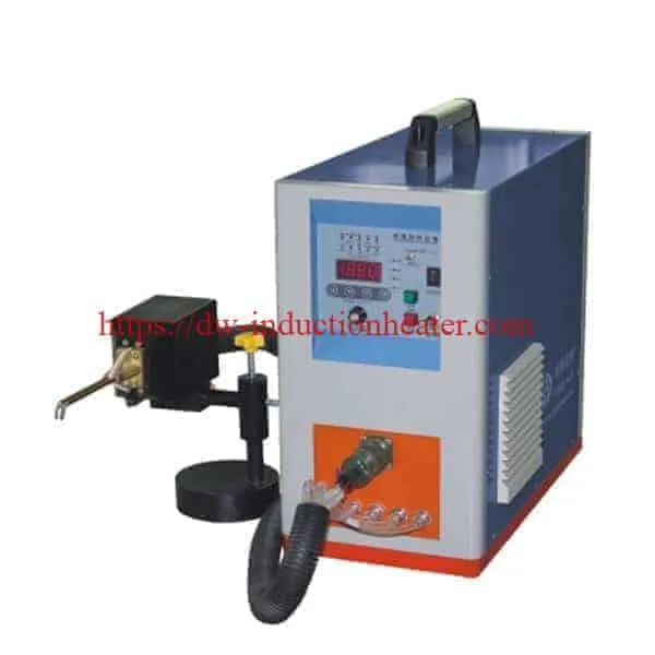
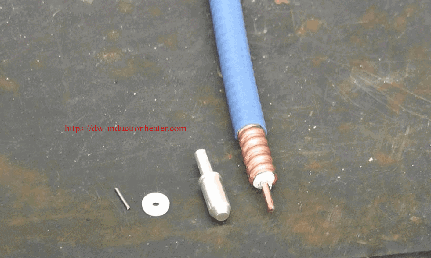
Equipment DW-UHF-6KW-III handheld induction brazing heater handheld inductino heaterMaterials • Copper coaxial cable • Plated copper connectors • Copper bullet-shaped internal connector • Copper pin-shaped internal connector • Solder wire • Carbon steel
Test 1: Soldering Copper Coax Center Conductor to Bullet-Shaped Center Pin Key Parameters Temperature: ~400°F (204°C) Power: 1.32 kW Time: 3 seconds for bullet connector
Test 2: Soldering Copper Coax center conductor to Needle-Shaped Center Pin Key Parameters Temperature: ~400°F (204°C) Power: 1.32 kW Time: 1.5 second for needle connector
Test 3: Soldering Copper Coax to the End Connector (Bullet-Shaped Center Pin) Key Parameters Temperature: ~400°F (204°C) Power: 1.8 kW Time: 30 seconds of heating time, followed by a 10 second cooling cycle
Test 4: Soldering Copper Coax to the End Connector (Needle-Shaped Center Pin) Key Parameters Temperature: ~400°F (204°C) Time: 30 seconds of heating time, followed by a 10 second cooling cycle
Process: For each type of center pin, the soldering process has two steps. First, soldering the center pin (bullet-shaped or needle-shaped) to the center conductor of the coaxial cable; and second, soldering the coaxial cable with the pin into the end connector Tests 1 and 2: Soldering copper coax center conductor to the connector center pin
  1. The internal connector pin (needle and bullet followed the same process) were assembled to the coaxial cable center conductor. A solder slug roughly ½ the length of the pin where the wire is to be soldered, was cut and placed in the receiving end of the center pin. The copper conductor of the coax was positioned to rest on the solder slug in the pin with light pressure downward.
  2. The assembly was placed into a two-turn induction coil, and power was turned on.
  3. As the solder melted, the copper conductor of the coax seated into the center pin. The assembly was held still for several more seconds as the solder cooled. Note: it is important to keep the solder joint still until it has cooled. If movement occurs, a “cold” solder joint can result.
Tests 3 and 4: Soldering copper screw-type end connector to the Center Pin
  1. Solder wire was wound around the corrugated flutes of the coax. The coax with solder was placed into the end connector.
  2. The assembly was placed into a u-shaped induction coil, and power was turned on.
  3. Heat time – 30 seconds for either assembly followed by a 10 second hold to let the alloy solidify.
Results/Benefits: The soldering was successful, and confirmed that induction soldering copper wire connectors is an excellent alternative to hand soldering.
  • Precise control of the time and temperature
  • Power on demand with rapid heat cycles
  • Repeatable process, not operator dependent
  • Safe heating with no open flames
  • Energy efficient heating
https://dw-inductionheater.com/induction-soldering-copper-wire-connectors.html?feed_id=239662&_unique_id=660b7791d841c

2024年3月30日星期六

high frequency induction soldering wire to connector

Objective The purpose of this test is to demonstrate the induction soldering wire to connector Recommended Equipment The recommended equipment for this test is the with the customized induction heating coil.  DW-UHF-6KW-I handheld induction heater
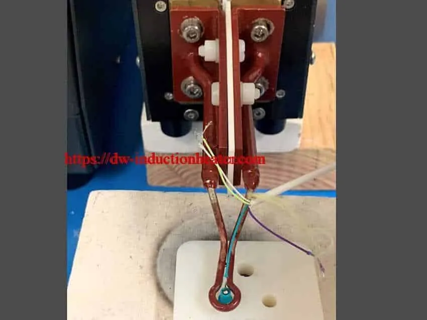
Key Parameters Power: Up to 0.48 kW Temperature: 392°F (200°C) Time: 1.5 seconds
Process and Results: This induction soldering wire to connector process was quick yet effective. The unit was run at 985 kHz, the reason for using such a high frequency was to couple into the small diameter of the wires. The whole process from the heat being turned on to the hardening of the solder took 1.5 seconds. Previously a soldering iron was being used to complete this task, however induction soldering was proven to be much faster and more efficient. The process can now be automated on an assembly line, because the system can remotely be turned on.
https://dw-inductionheater.com/high-frequency-induction-soldering-wire-to-connector.html?feed_id=239324&_unique_id=66089c76922a3

2023年9月25日星期一

Induction Soldering Wire of Co-axial

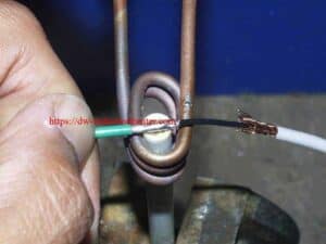
Induction Soldering Wire of Co-axial With High Frequency Heating Units Objective To solder center-conductor and shielding braid of wire assemblies to 500 (250) °F(°C). Material • Customer-supplied assemblies • Temperature indicating paint • Flux-cored solder wire Temperature 500 (250) °F (°C) Frequency 272 kHz Equipment DW-UHF-4.5kW induction heating system, equipped with a remote heat station containing two 0.33 μF capacitors. An induction heating coil designed and developed specifically for this application. Process A multi-turn helical coil is used and temperature-indicating paint is applied to the joint area. The wire assembly is placed over the induction heating coil, and RF power is applied. The time-to-temperature and the heating pattern on the part are established. The next wire assembly is placed on the coil, the assembly is heated and solder wire is fed into the joint. The assembly heats well and reaches 500 °F in 10 seconds. Results/Benefits • elimination of a crimp process • more reliable connections are made • faster process times induction soldering wire                 soldering wire together https://dw-inductionheater.com/induction-soldering-wire-of-co-axial.html?feed_id=227921&_unique_id=65123dae604a0
2023年8月14日星期一

Induction Soldering Copper Wire Connectors

Objective The objective of this application test is to determine heating times for induction soldering copper wire connectors onto a copper coaxial cable. The customer would like to replace hand soldering with soldering irons, with induction soldering. Hand soldering can be labor intensive, and the resulting solder joint is highly dependent on the skill of the operator. Induction soldering allows finite process control, and provides a consistent result.
Equipment DW-UHF-6KW-III handheld induction brazing heater handheld inductino heaterMaterials • Copper coaxial cable • Plated copper connectors • Copper bullet-shaped internal connector • Copper pin-shaped internal connector • Solder wire • Carbon steel
Test 1: Soldering Copper Coax Center Conductor to Bullet-Shaped Center Pin Key Parameters Temperature: ~400°F (204°C) Power: 1.32 kW Time: 3 seconds for bullet connector
Test 2: Soldering Copper Coax center conductor to Needle-Shaped Center Pin Key Parameters Temperature: ~400°F (204°C) Power: 1.32 kW Time: 1.5 second for needle connector
Test 3: Soldering Copper Coax to the End Connector (Bullet-Shaped Center Pin) Key Parameters Temperature: ~400°F (204°C) Power: 1.8 kW Time: 30 seconds of heating time, followed by a 10 second cooling cycle
Test 4: Soldering Copper Coax to the End Connector (Needle-Shaped Center Pin) Key Parameters Temperature: ~400°F (204°C) Time: 30 seconds of heating time, followed by a 10 second cooling cycle
Process: For each type of center pin, the soldering process has two steps. First, soldering the center pin (bullet-shaped or needle-shaped) to the center conductor of the coaxial cable; and second, soldering the coaxial cable with the pin into the end connector Tests 1 and 2: Soldering copper coax center conductor to the connector center pin
  1. The internal connector pin (needle and bullet followed the same process) were assembled to the coaxial cable center conductor. A solder slug roughly ½ the length of the pin where the wire is to be soldered, was cut and placed in the receiving end of the center pin. The copper conductor of the coax was positioned to rest on the solder slug in the pin with light pressure downward.
  2. The assembly was placed into a two-turn induction coil, and power was turned on.
  3. As the solder melted, the copper conductor of the coax seated into the center pin. The assembly was held still for several more seconds as the solder cooled. Note: it is important to keep the solder joint still until it has cooled. If movement occurs, a “cold” solder joint can result.
Tests 3 and 4: Soldering copper screw-type end connector to the Center Pin
  1. Solder wire was wound around the corrugated flutes of the coax. The coax with solder was placed into the end connector.
  2. The assembly was placed into a u-shaped induction coil, and power was turned on.
  3. Heat time – 30 seconds for either assembly followed by a 10 second hold to let the alloy solidify.
Results/Benefits: The soldering was successful, and confirmed that induction soldering copper wire connectors is an excellent alternative to hand soldering.
  • Precise control of the time and temperature
  • Power on demand with rapid heat cycles
  • Repeatable process, not operator dependent
  • Safe heating with no open flames
  • Energy efficient heating

2023年8月10日星期四

Induction Soldering Copper Wire Connectors

Objective The objective of this application test is to determine heating times for induction soldering copper wire connectors onto a copper coaxial cable. The customer would like to replace hand soldering with soldering irons, with induction soldering. Hand soldering can be labor intensive, and the resulting solder joint is highly dependent on the skill of the operator. Induction soldering allows finite process control, and provides a consistent result.
Equipment DW-UHF-6KW-III handheld induction brazing heater handheld inductino heaterMaterials • Copper coaxial cable • Plated copper connectors • Copper bullet-shaped internal connector • Copper pin-shaped internal connector • Solder wire • Carbon steel
Test 1: Soldering Copper Coax Center Conductor to Bullet-Shaped Center Pin Key Parameters Temperature: ~400°F (204°C) Power: 1.32 kW Time: 3 seconds for bullet connector
Test 2: Soldering Copper Coax center conductor to Needle-Shaped Center Pin Key Parameters Temperature: ~400°F (204°C) Power: 1.32 kW Time: 1.5 second for needle connector
Test 3: Soldering Copper Coax to the End Connector (Bullet-Shaped Center Pin) Key Parameters Temperature: ~400°F (204°C) Power: 1.8 kW Time: 30 seconds of heating time, followed by a 10 second cooling cycle
Test 4: Soldering Copper Coax to the End Connector (Needle-Shaped Center Pin) Key Parameters Temperature: ~400°F (204°C) Time: 30 seconds of heating time, followed by a 10 second cooling cycle
Process: For each type of center pin, the soldering process has two steps. First, soldering the center pin (bullet-shaped or needle-shaped) to the center conductor of the coaxial cable; and second, soldering the coaxial cable with the pin into the end connector Tests 1 and 2: Soldering copper coax center conductor to the connector center pin
  1. The internal connector pin (needle and bullet followed the same process) were assembled to the coaxial cable center conductor. A solder slug roughly ½ the length of the pin where the wire is to be soldered, was cut and placed in the receiving end of the center pin. The copper conductor of the coax was positioned to rest on the solder slug in the pin with light pressure downward.
  2. The assembly was placed into a two-turn induction coil, and power was turned on.
  3. As the solder melted, the copper conductor of the coax seated into the center pin. The assembly was held still for several more seconds as the solder cooled. Note: it is important to keep the solder joint still until it has cooled. If movement occurs, a “cold” solder joint can result.
Tests 3 and 4: Soldering copper screw-type end connector to the Center Pin
  1. Solder wire was wound around the corrugated flutes of the coax. The coax with solder was placed into the end connector.
  2. The assembly was placed into a u-shaped induction coil, and power was turned on.
  3. Heat time – 30 seconds for either assembly followed by a 10 second hold to let the alloy solidify.
Results/Benefits: The soldering was successful, and confirmed that induction soldering copper wire connectors is an excellent alternative to hand soldering.
  • Precise control of the time and temperature
  • Power on demand with rapid heat cycles
  • Repeatable process, not operator dependent
  • Safe heating with no open flames
  • Energy efficient heating
https://dw-inductionheater.com/induction-soldering-copper-wire-connectors.html?feed_id=222586&_unique_id=64d4cc3b4ff87

high frequency induction soldering wire to connector

Objective The purpose of this test is to demonstrate the induction soldering wire to connector Recommended Equipment The recommended equipment for this test is the with the customized induction heating coil.  DW-UHF-6KW-I handheld induction heater
Key Parameters Power: Up to 0.48 kW Temperature: 392°F (200°C) Time: 1.5 seconds
Process and Results: This induction soldering wire to connector process was quick yet effective. The unit was run at 985 kHz, the reason for using such a high frequency was to couple into the small diameter of the wires. The whole process from the heat being turned on to the hardening of the solder took 1.5 seconds. Previously a soldering iron was being used to complete this task, however induction soldering was proven to be much faster and more efficient. The process can now be automated on an assembly line, because the system can remotely be turned on.

2023年8月8日星期二

high frequency induction soldering wire to connector

Objective The purpose of this test is to demonstrate the induction soldering wire to connector Recommended Equipment The recommended equipment for this test is the with the customized induction heating coil.  DW-UHF-6KW-I handheld induction heater
Key Parameters Power: Up to 0.48 kW Temperature: 392°F (200°C) Time: 1.5 seconds
Process and Results: This induction soldering wire to connector process was quick yet effective. The unit was run at 985 kHz, the reason for using such a high frequency was to couple into the small diameter of the wires. The whole process from the heat being turned on to the hardening of the solder took 1.5 seconds. Previously a soldering iron was being used to complete this task, however induction soldering was proven to be much faster and more efficient. The process can now be automated on an assembly line, because the system can remotely be turned on.
https://dw-inductionheater.com/high-frequency-induction-soldering-wire-to-connector.html?feed_id=222286&_unique_id=64d1f08d31230

2023年7月10日星期一

high frequency induction soldering wire to connector

Objective The purpose of this test is to demonstrate the induction soldering wire to connector Recommended Equipment The recommended equipment for this test is the with the customized induction heating coil.  DW-UHF-6KW-I handheld induction heater
Key Parameters Power: Up to 0.48 kW Temperature: 392°F (200°C) Time: 1.5 seconds
Process and Results: This induction soldering wire to connector process was quick yet effective. The unit was run at 985 kHz, the reason for using such a high frequency was to couple into the small diameter of the wires. The whole process from the heat being turned on to the hardening of the solder took 1.5 seconds. Previously a soldering iron was being used to complete this task, however induction soldering was proven to be much faster and more efficient. The process can now be automated on an assembly line, because the system can remotely be turned on.

2023年6月16日星期五

high frequency induction soldering wire to connector

Objective The purpose of this test is to demonstrate the induction soldering wire to connector Recommended Equipment The recommended equipment for this test is the with the customized induction heating coil.  DW-UHF-6KW-I handheld induction heater
Key Parameters Power: Up to 0.48 kW Temperature: 392°F (200°C) Time: 1.5 seconds
Process and Results: This induction soldering wire to connector process was quick yet effective. The unit was run at 985 kHz, the reason for using such a high frequency was to couple into the small diameter of the wires. The whole process from the heat being turned on to the hardening of the solder took 1.5 seconds. Previously a soldering iron was being used to complete this task, however induction soldering was proven to be much faster and more efficient. The process can now be automated on an assembly line, because the system can remotely be turned on.

2023年6月14日星期三

Induction Soldering Wire of Co-axial

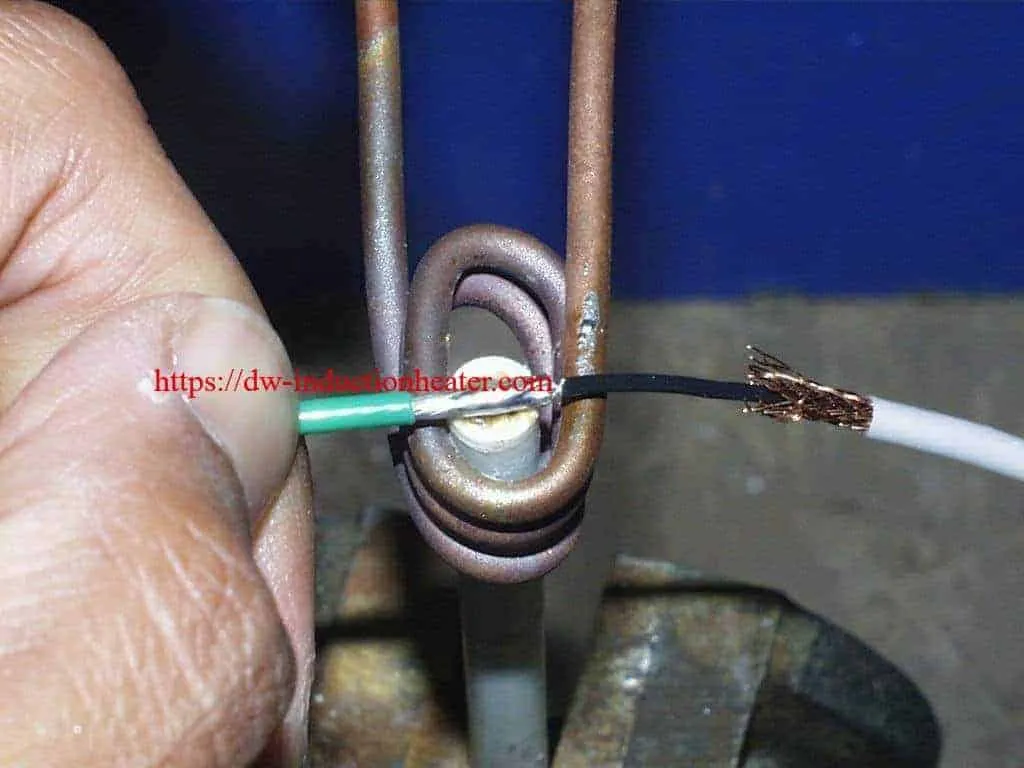
Induction Soldering Wire of Co-axial With High Frequency Heating Units Objective To solder center-conductor and shielding braid of wire assemblies to 500 (250) °F(°C). Material • Customer-supplied assemblies • Temperature indicating paint • Flux-cored solder wire Temperature 500 (250) °F (°C) Frequency 272 kHz Equipment DW-UHF-4.5kW induction heating system, equipped with a remote heat station containing two 0.33 μF capacitors. An induction heating coil designed and developed specifically for this application. Process A multi-turn helical coil is used and temperature-indicating paint is applied to the joint area. The wire assembly is placed over the induction heating coil, and RF power is applied. The time-to-temperature and the heating pattern on the part are established. The next wire assembly is placed on the coil, the assembly is heated and solder wire is fed into the joint. The assembly heats well and reaches 500 °F in 10 seconds. Results/Benefits • elimination of a crimp process • more reliable connections are made • faster process times induction soldering wire                 soldering wire together

2023年6月4日星期日

Induction Soldering Wire of Co-axial

Induction Soldering Wire of Co-axial With High Frequency Heating Units Objective To solder center-conductor and shielding braid of wire assemblies to 500 (250) °F(°C). Material • Customer-supplied assemblies • Temperature indicating paint • Flux-cored solder wire Temperature 500 (250) °F (°C) Frequency 272 kHz Equipment DW-UHF-4.5kW induction heating system, equipped with a remote heat station containing two 0.33 μF capacitors. An induction heating coil designed and developed specifically for this application. Process A multi-turn helical coil is used and temperature-indicating paint is applied to the joint area. The wire assembly is placed over the induction heating coil, and RF power is applied. The time-to-temperature and the heating pattern on the part are established. The next wire assembly is placed on the coil, the assembly is heated and solder wire is fed into the joint. The assembly heats well and reaches 500 °F in 10 seconds. Results/Benefits • elimination of a crimp process • more reliable connections are made • faster process times induction soldering wire                 soldering wire together
2023年5月25日星期四

Induction Soldering Copper Wire Connectors

Objective The objective of this application test is to determine heating times for induction soldering copper wire connectors onto a copper coaxial cable. The customer would like to replace hand soldering with soldering irons, with induction soldering. Hand soldering can be labor intensive, and the resulting solder joint is highly dependent on the skill of the operator. Induction soldering allows finite process control, and provides a consistent result.
Equipment DW-UHF-6KW-III handheld induction brazing heater handheld inductino heaterMaterials • Copper coaxial cable • Plated copper connectors • Copper bullet-shaped internal connector • Copper pin-shaped internal connector • Solder wire • Carbon steel
Test 1: Soldering Copper Coax Center Conductor to Bullet-Shaped Center Pin Key Parameters Temperature: ~400°F (204°C) Power: 1.32 kW Time: 3 seconds for bullet connector
Test 2: Soldering Copper Coax center conductor to Needle-Shaped Center Pin Key Parameters Temperature: ~400°F (204°C) Power: 1.32 kW Time: 1.5 second for needle connector
Test 3: Soldering Copper Coax to the End Connector (Bullet-Shaped Center Pin) Key Parameters Temperature: ~400°F (204°C) Power: 1.8 kW Time: 30 seconds of heating time, followed by a 10 second cooling cycle
Test 4: Soldering Copper Coax to the End Connector (Needle-Shaped Center Pin) Key Parameters Temperature: ~400°F (204°C) Time: 30 seconds of heating time, followed by a 10 second cooling cycle
Process: For each type of center pin, the soldering process has two steps. First, soldering the center pin (bullet-shaped or needle-shaped) to the center conductor of the coaxial cable; and second, soldering the coaxial cable with the pin into the end connector Tests 1 and 2: Soldering copper coax center conductor to the connector center pin
  1. The internal connector pin (needle and bullet followed the same process) were assembled to the coaxial cable center conductor. A solder slug roughly ½ the length of the pin where the wire is to be soldered, was cut and placed in the receiving end of the center pin. The copper conductor of the coax was positioned to rest on the solder slug in the pin with light pressure downward.
  2. The assembly was placed into a two-turn induction coil, and power was turned on.
  3. As the solder melted, the copper conductor of the coax seated into the center pin. The assembly was held still for several more seconds as the solder cooled. Note: it is important to keep the solder joint still until it has cooled. If movement occurs, a “cold” solder joint can result.
Tests 3 and 4: Soldering copper screw-type end connector to the Center Pin
  1. Solder wire was wound around the corrugated flutes of the coax. The coax with solder was placed into the end connector.
  2. The assembly was placed into a u-shaped induction coil, and power was turned on.
  3. Heat time – 30 seconds for either assembly followed by a 10 second hold to let the alloy solidify.
Results/Benefits: The soldering was successful, and confirmed that induction soldering copper wire connectors is an excellent alternative to hand soldering.
  • Precise control of the time and temperature
  • Power on demand with rapid heat cycles
  • Repeatable process, not operator dependent
  • Safe heating with no open flames
  • Energy efficient heating

关注者

我的简介

我的照片
HLQ induction heating machine manufacturer provides the service of induction brazing,melting,hot forming,hardening surface,annealing,shrink fitting,PWHT,etc.