2022年9月30日星期五
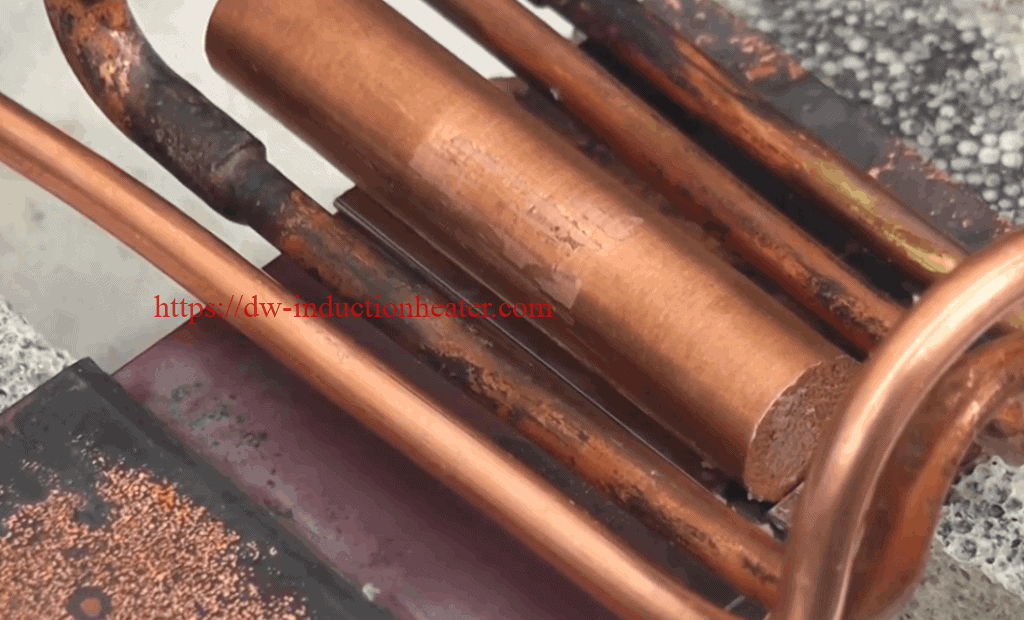
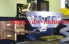
Induction Soldering Aluminum Housing

Aluminum Tubes Induction Brazing
The advantages of induction brazing of aluminum vs. torch or flame brazing
The low melting temperature of aluminum base metals coupled with the narrow temperature process window of the braze alloys used is a challenge when torch brazing. The lack of color change while heating aluminum does not provide braze operators any visual indication that the aluminum has reached the proper brazing temperature. Braze operators introduce a number of variables when torch brazing. Among these include torch settings and flame type; distance from torch to parts being brazed; location of flame relative to parts being joined; and more. Reasons to consider using induction heating when brazing aluminum include:- Quick, rapid heating
- Controlled, precise heat control
- Selective (localized) heat
- Production line adaptability and integration
- Improved fixture life and simplicity
- Repeatable, reliable brazed joints
- Improved safety
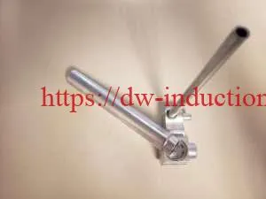 For a typical brazed aluminum tube joint, an operator installs an aluminum braze ring, often containing flux, on the aluminum tube and inserts this into another expanded tube or a block fitting. The parts are then placed into an induction coil and heated. In a normal process, the braze filler metals melt and flow into the joint interface due to capillary action.
Why induction braze vs. torch braze aluminum components?
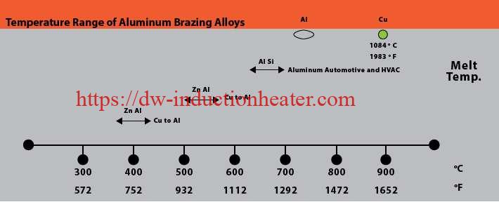
First, a little background on common aluminum alloys prevalent today and the common aluminum braze and solders used for joining. Brazing aluminum components is much more challenging than brazing copper components. Copper melts at 1980°F (1083°C) and it changes color as it is heated. Aluminum alloys often used in HVAC systems start to melt at approximately 1190°F (643°C) and do not provide any visual cues, such as color changes, as it heats.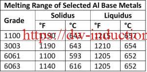 Very precise temperature control is required as the difference in the melting and brazing temperatures for aluminum, dependent upon the aluminum base metal, braze filler metal, and mass of the components to be brazed. For example, The temperature difference between solidus temperature of two common aluminum alloys, 3003 series aluminum, and 6061 series aluminum, and the liquid’s temperature of frequently used BAlSi-4 braze alloy is 20°F – a very narrow temperature process window, thus necessitating precise control. The selection of base alloys is extremely important with aluminum systems that are being brazed. The best practice is to braze at a temperature that is below the solidus temperature of the alloys the make up the components being brazed together.
| AWS A5.8 Classification | Nominal Chemical Composition | Solidus °F (°C) | Liquidus °F(°C) | Brazing Temperature |
| BAISi-3 | 86% Al 10%Si 4%Cu | 970 (521) | 1085 (855) | 1085~1120 °F |
| BAISI-4 | 88% aL 12%Si | 1070 (577) | 1080 (582) | 1080~1120 °F |
| 78 Zn 22%Al | 826 (441) | 905(471) | 905~950 °F | |
| 98% Zn 2%Al | 715(379) | 725(385) | 725~765 °F |
 Aluminum forms a tough oxide layer during brazing, so the use of flux is essential. Fluxing aluminum components can be done separately prior to brazing or an aluminum brazing alloy containing flux can be incorporated into the brazing process. Depending upon the type of flux used (corrosive vs. non-corrosive), an additional step may be required if the flux residue must be removed after brazing. Consult with a braze and flux manufacturer to get recommendations on brazing alloy and flux based on the materials being joined and the expected brazing temperatures.
Aluminum Tubes Induction Brazing
Induction Brazing Principle-Theory
Induction Brazing Technology
Induction Brazing Principle|Theory Brazing and soldering are processes of joining similar or dissimilar materials using a compatible a filler material. Filler metals include lead, tin, copper, silver, nickel and their alloys. Only the alloy melts and solidifies during these processes to join the work piece base materials. The filler metal is pulled into the joint by capillary action. Soldering processes are conducted below 840°F (450°C) while brazing applications are conducted at temperatures above 840°F (450°C) up to 2100°F (1150°C).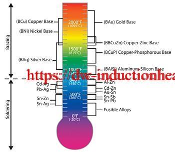 The success of these processes depends upon the assembly’s design, clearance between the surfaces to be joined, cleanliness, process control and the correct selection of equipment needed to perform a repeatable process.
Cleanliness is ordinarily obtained by introducing a flux which covers and dissolves dirt or oxides displacing them from the braze joint.
Many operations are now conducted in a controlled atmosphere with a blanket of inert gas or combination of inert / active gasses to shield the operation and eliminate the need for a flux. These methods have been proven on a wide variety of material and part configurations replacing or complimenting atmosphere furnace technology with a just in time - single piece flow process.
Brazing Filler Materials
Brazing filler metals can come in a variety of forms, shapes, sizes and alloys depending on their intended use. Ribbon, preformed rings, paste, wire and preformed washers are just a few of the shapes and forms alloys that can be found.
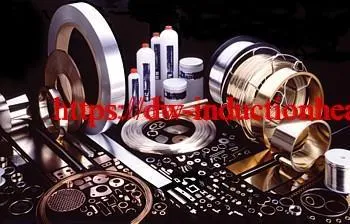 The decision to use a particular alloy and/or shape is largely dependent on the parent materials to be joined, placement during processing and the service environment for which the final product is intended.
Clearance Affects Strength
Clearance between the faying surfaces to be joined determines the amount of braze alloy, capillary action / penetration of the alloy and subsequently the strength of the finished joint. The best fit up condition for conventional silver brazing applications are 0.002 inches (0.050 mm) to 0.005 inches (0.127 mm) total clearance. Aluminum is typically 0.004 inches (0.102 mm) to 0.006 inches (0.153 mm). Larger clearances up to 0.015 inches (0.380 mm) usually lack sufficient capillary action for a successful braze.
Brazing with copper (above 1650°F / 900°C) requires the joint tolerance kept to an absolute minimum and in some cases press fit at ambient temperatures to assure minimum joint tolerances while at the brazing temperature.
Induction Heating Theory
Induction systems provide a convenient and precise way to quickly and efficiently heat a selected area of an assembly. Consideration must be given to the selection of power supply operating frequency, power density (kilowatt applied per square inch), heating time, and induction coil design to provide the required depth of heating in a specific braze joint.
Induction heating is non-contact heating by means of transformer theory. The power supply is an AC source to the induction coil that becomes the primary windings of the transformer while the part to be heated is the transformer’s secondary. The work piece heats by the base materials’ inherent electrical resistivity to the induced current flowing in the assembly.
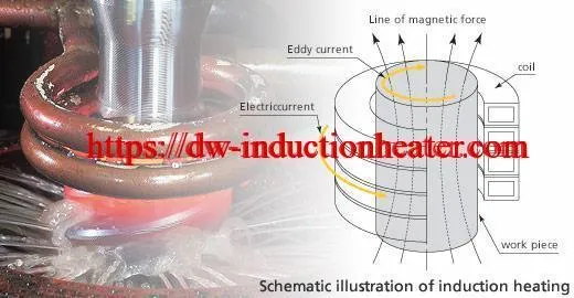 Current passing through an electrical conductor (the workpiece) results in heating as current meets resistance to its flow. These losses are low in current flowing through aluminum, copper and their alloys. These non-ferrous materials require additional power to heat than their carbon steel counterpart.
The alternating current tends to flow on the surface. The relationship between the frequency of the alternating current and the depth it penetrates the part is known as the reference depth of heating. Part diameter, material type and wall thickness can have an effect on heating efficiency based on the reference depth.
Induction Handheld Brazing Copper To Steel Tube
Induction Handheld Brazing Copper To Steel Tube
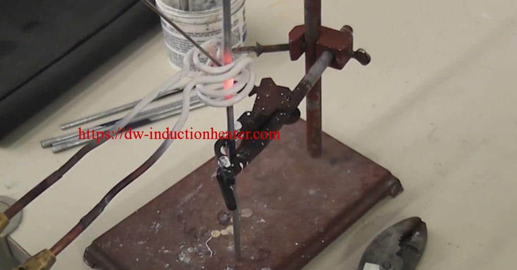 Objective
Braze copper cylinders, copper wires, and steel tubes in under 20 seconds using the DW-UHF-6KW-III handheld induction heating system.
Equipment
DW-UHF-6KW-III handheld induction heating system
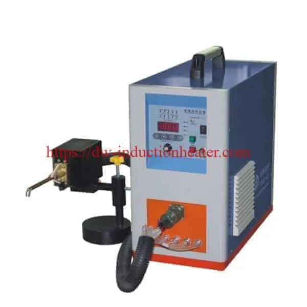 Test 1
Materials
• Copper cylinder to copper wire.
Power: 6.6kW
Temperature: 871° C (1600° F)
Time: 20 sec
Test 2
Materials
• Copper cylinder to steel tube.
Power: 10 kW
Temperature: 871° C (1600° F)
Time: 10 to 11 sec
Results and Conclusions:
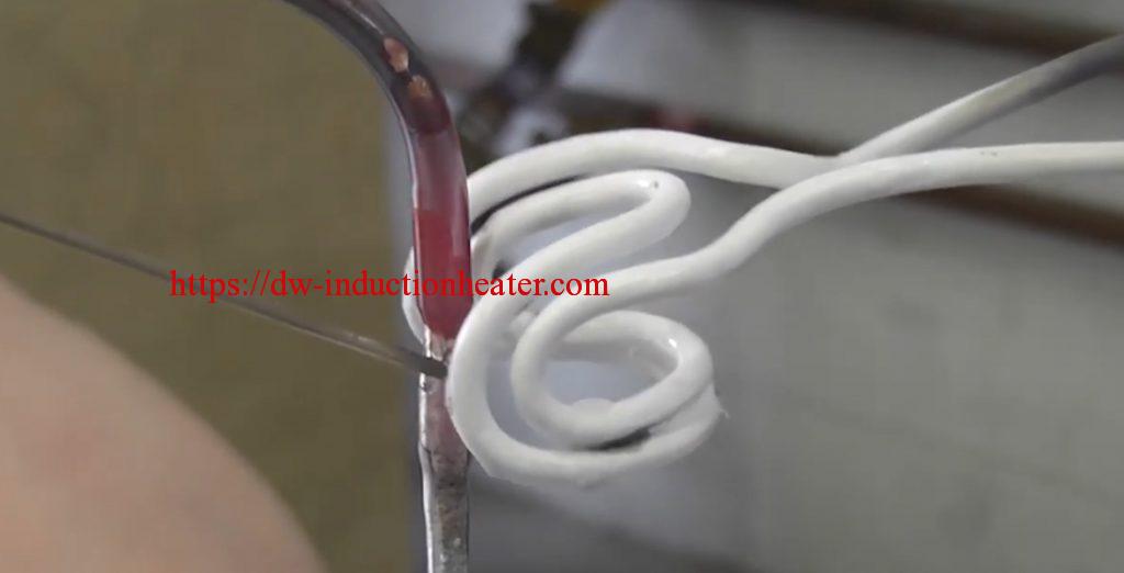
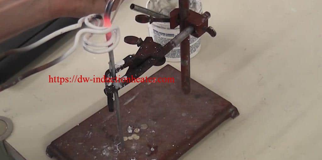
It is recommended to use brazing alloy preforms / rings instead of a brazing rod. This allows the user to use both hands to hold the U-Braze. It also improves the quality of the braze and repeatability by distributing the correct amount of alloy all around the braze joint every time.
When brazing copper to steel, it is best to preheat the copper to avoid overheating the steel piece since the copper is harder to heat.
 [wpforms id="3947"]
Induction Heating Solutions For Cancer Research
Induction Bending Pipe-Tube
Induction bending pipe
What is Induction Bending?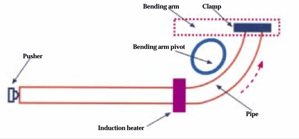 Induction Bending is a precisely controlled and efficient piping bending technique. Local heating using high frequency induced electrical power is applied during the induction bending process. Pipes, tubes, and even structural shapes (channels, W & H sections) can be bent efficiently in an induction bending machine. Induction bending is also known as hot bending, incremental bending, or high-frequency bending. For bigger pipe diameters, when cold bending methods are limited, Induction bending is the most preferable option. Around the pipe to be bent, an induction coil is placed that heats the pipe circumference in the range of 850 – 1100 degrees Celsius.
An induction bending pipe/tube machine is sketched in the photo. After positioning the pipe and securely clamping its ends, power is applied to a solenoid-type inductor that provides circumferential heating of the pipe in the area where it will be bent. When a temperature distribution that provides sufficient ductility to the metal at the region of bending has been attained, the pipe is then pushed through the coil at a certain speed. The pipe’s leading end, which is clamped to the bending arm, is subjected to a bending moment. The bending arm can pivot up to 180°.
In induction bending of carbon steel pipe, the length of the heated band usually is 25 to 50 mm (1 to 2 in.), with a required bending temperature in the 800 to 1080°C (1470 to 1975°F) range. As pipe passes through the inductor, it bends within the hot, ductile region by an amount dictated by the radius of the bending arm pivot, while each end of the heated region is supported by a cold, nonductile section of pipe. Depending upon the application,
bending speed can range from 13 to 150 mm/min (0.5 to 6 in./min). In some applications where larger radii are required, a set of rolls is used to provide the required bending force instead of a bending arm pivot.After the bending operation, the pipe is cooled to ambient temperature using a water spray, forced air, or natural cooling in air. A stress relief or temper can then be conducted to obtain required post-bend properties.
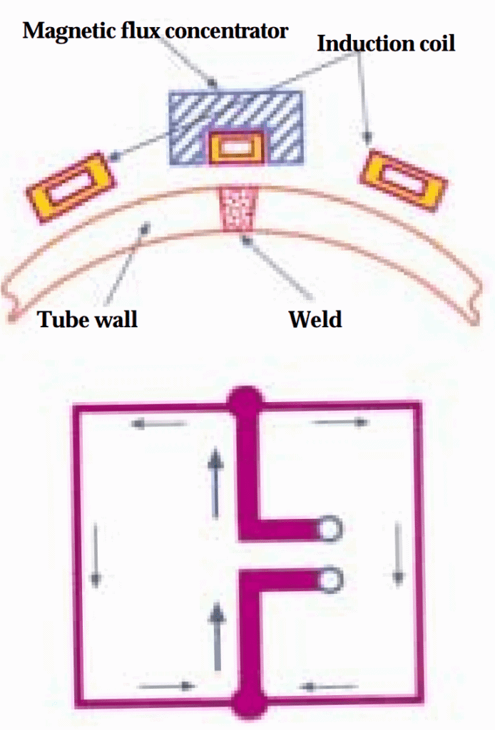 Wall thinning: Induction heating provides rapid circumferential heating of selected areas of the pipe, consuming a minimum amount of energy compared with other hot bending processes in which the entire pipe is heated. There also are other important benefits provided by induction tube bending. These include highly predictable shape distortion (ovality) and wall thinning. Minimization and predictability of wall thinning are particularly critical when producing tubes and pipes for applications that must meet high-pressure requirements,such as nuclear power and oil/gas pipelines. For example, oil and gas pipeline ratings are based on wall thickness. During bending, the outer side of the bend is in tension and has a reduced cross section, while the inner side is in compression. When conventional heating is used in bending, the cross section of the outer side of the bend area often is reduced by 20% or more resulting in a corresponding reduction of the total pipeline pressure rating.The pipe bend becomes the pipeline's pressure-limiting factor.
With induction heating, the reduction in cross section is reduced to typically 11% due to very even heating, an optimized bending program via a computerized bending machine, and a narrow plasticized (ductile) zone. Consequently, induction heating not only reduces production costs and increases bend quality, but also reduces total pipeline cost.
Other important advantages of induction bending: it is not labor intensive, it has little effect on surface finish, and it has the ability to make small radii, which enables bending of thinwall tubes and the production of multiradius curves/multiple bends in one pipe.
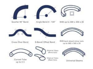 Benefits of Induction Bending:
- Large radii for smooth flow of fluid.
- Cost efficiency, straight material is less costly than standard components (e.g. elbows) and bends can be produced faster than standard components can be welded.
- Elbows can be replaced by larger radius bends where applicable and subsequently friction, wear and pump energy can be reduced.
- Induction bending reduces the number of welds in a system. It removes welds at the critical points (the tangents) and improves the ability to absorb pressure and stress.
- Induction bends are stronger than elbows with uniform wall thickness.
- Less non-destructive testing of welds, such as X-ray examination will save cost.
- Stock of elbows and standard bends can be greatly reduced.
- Faster access to base materials. Straight pipes are more readily available than elbows or standard components and bends can almost always be produced cheaper and faster.
- A limited amount of tools is needed (no use of thorns or mandrels as required in cold bending).
- Induction bending is a clean process. No lubrication is needed for the process and water needed for the cooling is recycled.
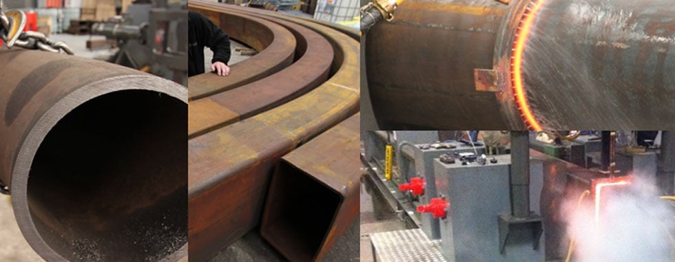
ADVANTAGES OF USING INDUCTION BENDING
- Infinitely variable bend radius, offering optimum design flexibility.
- Superior quality in terms of ovality, wall thinning and surface finish.
- Avoids the need for components with an elbow, allowing cheaper, more readily available straight materials to be utilised.
- A stronger end product than elbows with a uniform wall thickness.
- Large radius bend capability reduces friction and wear.
- Surface quality of bent material is not relevant in terms of suitability for use.
- Quicker production times than the welding of separate components.
- No cutting, rounding-up, match boring, fitting or heat treating/welding of forged fittings.
- Pipe and other sections can be curved to smaller radii than with cold bending techniques.
- Material surface unaffected/unblemished by the process.
- Multiple bends possible on a single length of pipe.
- Reduced welding requirement with compound bends, improving finished pipework integrity.
- Welds avoided at critical points.
- Less need for non-destructive testing, driving costs further down.
- Faster and more energy efficient than traditional fire/hot slab bending methods.
- Process eliminates the need for sand filling, mandrels or formers.
- A clean, lubricant-free process.
- Bend specification changes are possible right up to the last minute before production.
- Reduced need for formal on-site inspection of welded joint integrity.
- Faster repair and maintenance lead times, due to relative ease of producing replacement induction-bent pipes or tubes.
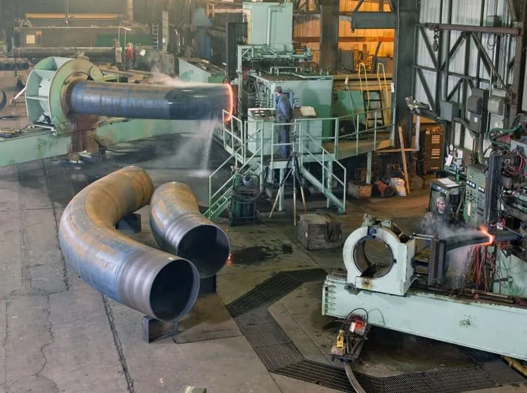
2022年9月29日星期四
Induction Brazing Machine
|
Series |
Model |
Input power Max |
Input current Max |
Oscillate frequency |
Input Voltage |
Duty cycle |
|
|
M
.
F
. |
DW-MF-15 Induction Generator |
15KW |
23A |
1K-20KHZ
According to the application |
3*380V
380V±20% |
100% |
|
|
DW-MF-25 Induction Generator |
25KW |
36A |
|||||
|
DW-MF-35Induction Generator |
35KW |
51A |
|||||
|
DW-MF-45 Induction Generator |
45KW |
68A |
|||||
|
DW-MF-70 Induction Generator |
70KW |
105A |
|||||
|
DW-MF-90 Induction Generator |
90KW |
135A |
|||||
|
DW-MF-110 Induction Generator |
110KW |
170A |
|||||
|
DW-MF-160 Induction Generator |
160KW |
240A |
|||||
|
DW-MF-45 Induction Heating Rod Forging Furnace |
45KW |
68A |
1K-20KHZ |
3*380V
380V±20% |
100% |
||
|
DW-MF-70 Induction Heating Rod Forging Furnace |
70KW |
105A |
|||||
|
DW-MF-90 Induction Heating Rod Forging Furnace |
90KW |
135A |
|||||
|
DW-MF-110 Induction Heating Rod Forging Furnace |
110KW |
170A |
|||||
|
DW-MF-160 Induction Heating Rod Forging Furnace |
160KW |
240A |
|||||
|
DW-MF-15 Induction Melting Furnace |
15KW |
23A |
1K-20KHZ |
3*380V
380V±20% |
100% |
||
|
DW-MF-25 Induction Melting Furnace |
25KW |
36A |
|||||
|
DW-MF-35 Induction Melting Furnace |
35KW |
51A |
|||||
|
DW-MF-45 Induction Melting Furnace |
45KW |
68A |
|||||
|
DW-MF-70 Induction Melting Furnace |
70KW |
105A |
|||||
|
DW-MF-90 Induction Melting Furnace |
90KW |
135A |
|||||
|
DW-MF-110 Induction Melting Furnace |
110KW |
170A |
|||||
|
DW-MF-160 Induction Melting Furnace |
160KW |
240A |
|||||
|
DW-MF-110 Induction Hardening Equipment |
110KW |
170A |
1K-8KHZ |
3*380V
380V±20% |
100% |
||
|
DW-MF-160Induction Hardening Equipment |
160KW |
240A |
|||||
|
H
.
F
. |
DW-HF-04 Series |
DW-HF-4KW-A |
4KVA |
15A |
100-250KHZ |
Single phase 220V |
80% |
|
DW-HF-15 Series |
DW-HF-15KW-A
DW-HF-15KW-B |
15KVA |
32A |
30-100KHZ |
Single phase 220V |
80% |
|
|
DW-HF-25 Series |
DW-HF-25KW-A
DW-HF-25KW-B |
25KVA |
23A |
20-80KHZ |
3*380V
380V±10% |
100% |
|
|
DW-HF-35 Series |
DW-HF-35KW-B |
35KVA |
51A |
||||
|
DW-HF-45 Series |
DW-HF-45KW-B |
45KVA |
68A |
||||
|
DW-HF-60 Series |
DW-HF-60KW-B |
60KVA |
105A |
||||
|
DW-HF-80 Series |
DW-HF-80KW-B |
80KVA |
130A |
||||
|
DW-HF-90 Series |
DW-HF-90KW-B |
90KVA |
160A |
||||
|
DW-HF-120 Series |
DW-HF-120KW-B |
120KVA |
200A |
||||
|
U
.
H
.
F
.
|
DW-UHF-3.2KW |
3.2KW |
13A |
1.1-2.0MHZ |
Single phase220V
±10% |
100% |
|
|
DW-UHF-4.5KW |
4.5KW |
20A |
|||||
|
DW-UHF-045T |
4.5KW |
20A |
|||||
|
DW-UHF-045L |
4.5KW |
20A |
|||||
|
DW-UHF-6.0KW |
6.0KW |
28A |
|||||
|
DW-UHF-06A |
6.0KW |
28A |
|||||
|
DW-UHF-6KW-B |
6.0KW |
28A |
|||||
|
DW-UHF-10KW |
10KW |
15A |
100-500KHZ |
3*380V
380V±10% |
100% |
||
|
DW-UHF-20KW |
20KW |
30A |
50-250KHZ |
||||
|
DW-UHF-30KW |
30KW |
45A |
50-200KHZ |
||||
|
DW-UHF-40KW |
40KW |
60A |
50-200KHZ |
||||
|
DW-UHF-60KW |
60KW |
90A |
50-150KHZ |
||||
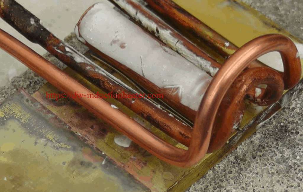
induction Brazing copper rods to brass strips

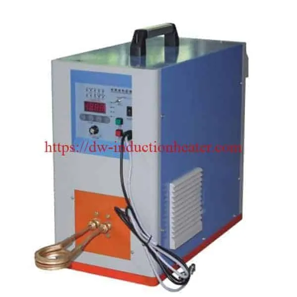 Two turn open end conveyor coil
Materials
• Copper coupon plate and copper rod
• Braze wire – EZ Flo 45
• Braze alloy – 45% Silver, 1/32 DIA
- induction brazing Strong durable joints
- Selective and precise heat zone, resulting in less part distortion and joint stress than welding
- Less oxidation
- Faster heating cycles
- More consistent results and suitability for large volume production, without the need for batch processing
- Safer than flame brazing
Handheld Induction Brazing HVAC Pipes of Heat Exchangers
Fast Handheld Induction Brazing HVAC Pipes System of Heat Exchangers
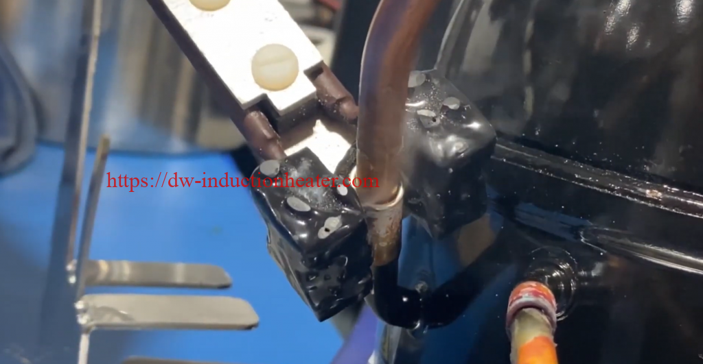 Induction brazing is the process of joining two or more metals using induction heating. Induction heating utilizes the electromagnetic field to provide heat without contact or flame. Induction brazing is more localized, repeatable, and easier to automate compared to traditional torch brazing.
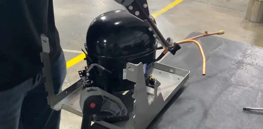 The principle of induction brazing is similar to the transformer principle, where the inductor is the primary winding and the part to be heated acts as a single turn secondary winding.
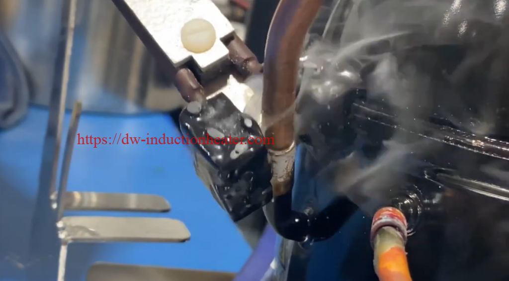 Using induction brazing rather than a conventional torch can increase the quality of joints and shorten the time necessary for each braze; however, the ease of creating a reproducible process makes induction brazing ideal for serial, high volume production processes such as induction brazing of heat exchangers. Brazing the bent copper tubing on heat exchangers can be tedious and time consuming because joint quality is critical and there are so many joints. Induction power could be your best solution to maintain quality without sacrificing production speed. Precisely controlled, powerful generators from HLQ provide heat exactly where you need it without causing distortion, ensuring that your production process is accurate and fast. Whether your heat exchangers are large, medium or small, in the plant or in the field, HLQ makes an induction brazing generator to meet your specific needs. Brazing can be done manually or with the aid of automation.
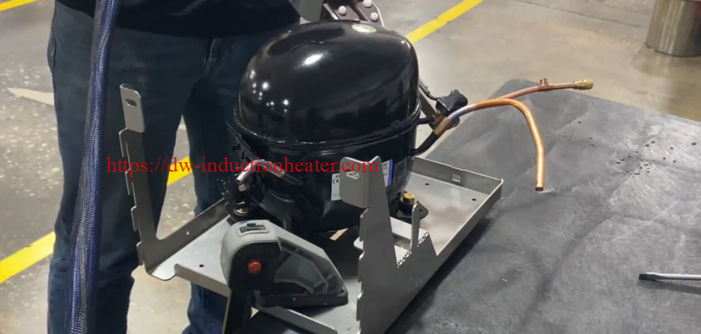
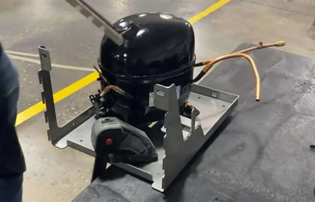
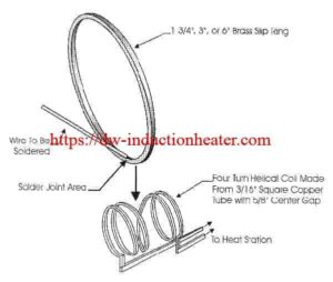
Induction Soldering Brass Rings
induction brazing steel tube to copper tube
High Frequency Induction Brazing Steel Tube to Copper Tube
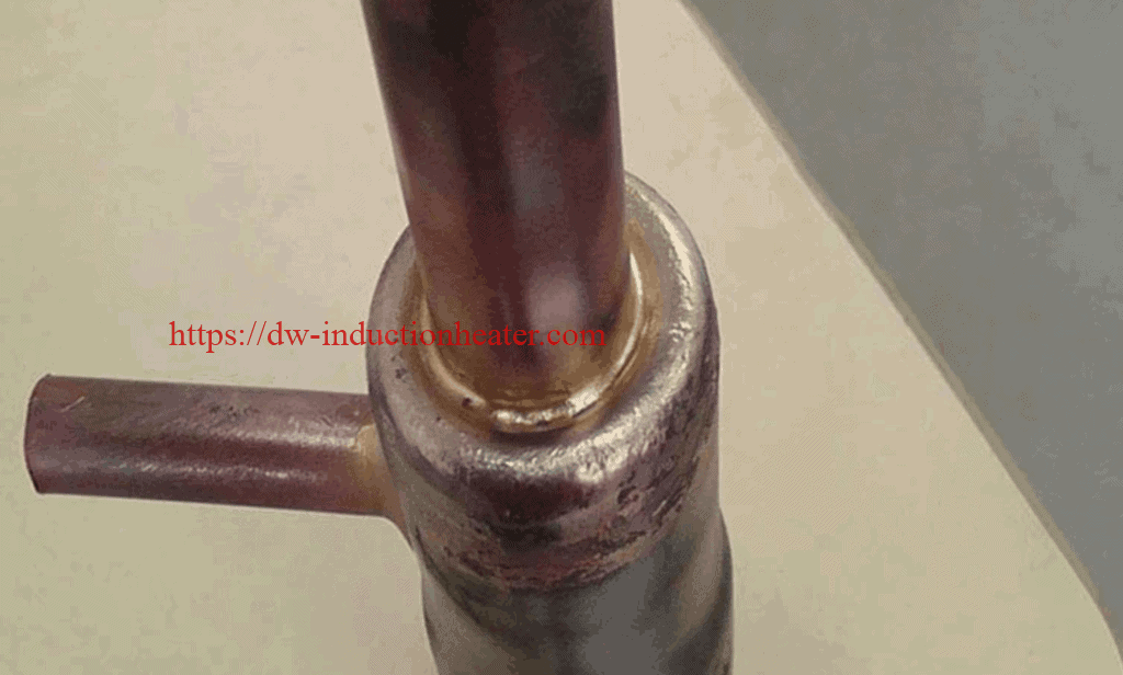
Objective The goal is to braze a steel tube to a copper tube in 60 seconds using flux and brazing alloy.- The assembly section was pre-assembled and fluxed (B-1) then located in the two diameter coil with a single pre-formed alloy ring set at the interface area.
- Alloy flow and joint completed in 60 seconds.
- The material was cooled in water following the completion of induction brazing.
- The joint was then cross-sectioned to validate that the brazing process had produced a strong, high quality joint.
- Strong durable joints with induction heating
- Selective and precise heat zone, resulting in less part distortion and joint stress than welding
- Less oxidation
- Faster heating cycles
- More consistent results and suitability for large volume production, without the need for batch processing
- Safer than flame brazing
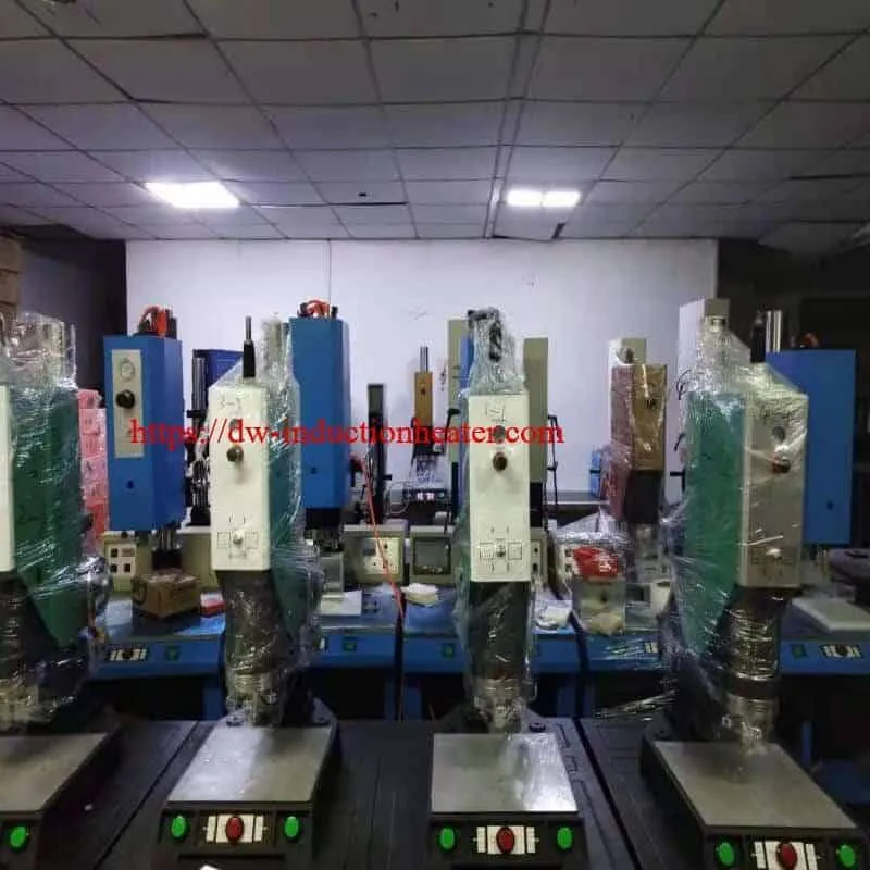
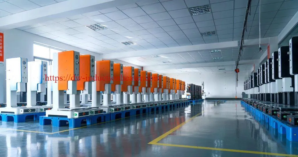
Ultrasonic Plastic Welding Machine For Bonding Thermoplastic Parts
Ultrasonic plastic welding machine | ultrasonic thermoplastic welder | ultra sonic plastic welding equipment with Automatic Frequency Chasing
Ultrasonic plastic welding is an industrial technique whereby high-frequency ultrasonic acoustic vibrations are locally applied to workpieces being held together under pressure to create a solid-state weld. It is commonly used for plastics and metals, and especially for joining dissimilar materials. In ultrasonic welding, there are no connective bolts, nails, soldering materials, or adhesives necessary to bind the materials together. When applied to metals, a notable characteristic of this method is that the temperature stays well below the melting point of the involved materials thus preventing any unwanted properties which may arise from high temperature exposure of the materials.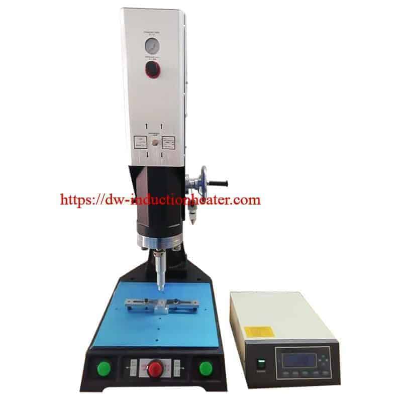
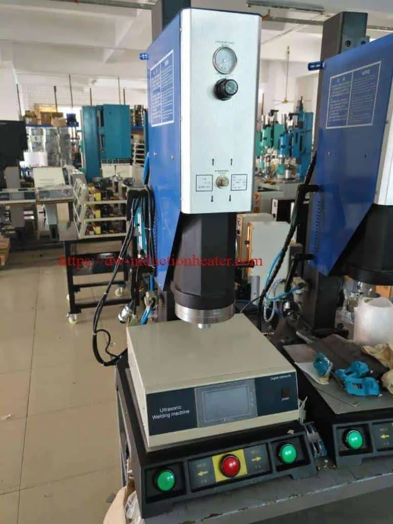 ♦Fully automatic frequency chasing, suitable for various sizes of welding die and different design mold, automatic chasing frequency range:±400HZ
Example: 15KHZ ultrasonic, mold frequency in 14.4-15.2KHZ can Automatic frequency traceability
♦The use of CPU computer to monitor various programs is fast and adaptable. The built-in protection system "system protection monitoring" function will respond to the following situations: the temperature is too high and the pressure is too high, which leads to overload. Excessive current of ultrasonic generator, loosening of solder head, transducer or transducer, failure of generator circuit, etc.
♦Automatic tuning enables the ultrasonic generator to automatically track and compensate for changes in welding head frequency. When the temperature is too high, wear on the surface of the welding head or debris on the head, this frequency change will occur.
♦Built-in automatic constant amplitude system. The ultrasonic amplitude can be adjusted from 50% to 100% stepless to adapt to different welding work.
♦With IGBT, the reaction speed is 100 times faster than that of traditional silica gel power tube.
| Model | 1520A | 1526A | 1532A | 1542A |
| Frequency | 15KHz | |||
| Power | 2000W | 2600W | 3200W | 4200W |
| Voltage | 220V | |||
| Capacity | 10-20 times/min | |||
| Driving form | Pneumatic | |||
| Stroke Length(Horn Journy) | 75mm | 100mm | ||
| Output Time | 0.01-9.99S Adjustable | |||
| Welding Area | Φ100 | Φ200 | Φ300 | Φ400 |
| Electricity | AC | |||
| Control mode | Numerical control | |||
| Working air pressure | 1-7 Bar | |||
| Weight | 90KG | 90KG | 90KG | 120KG |
| Dimensions | 450*750*1100mm | 760*1000*1950mm | ||
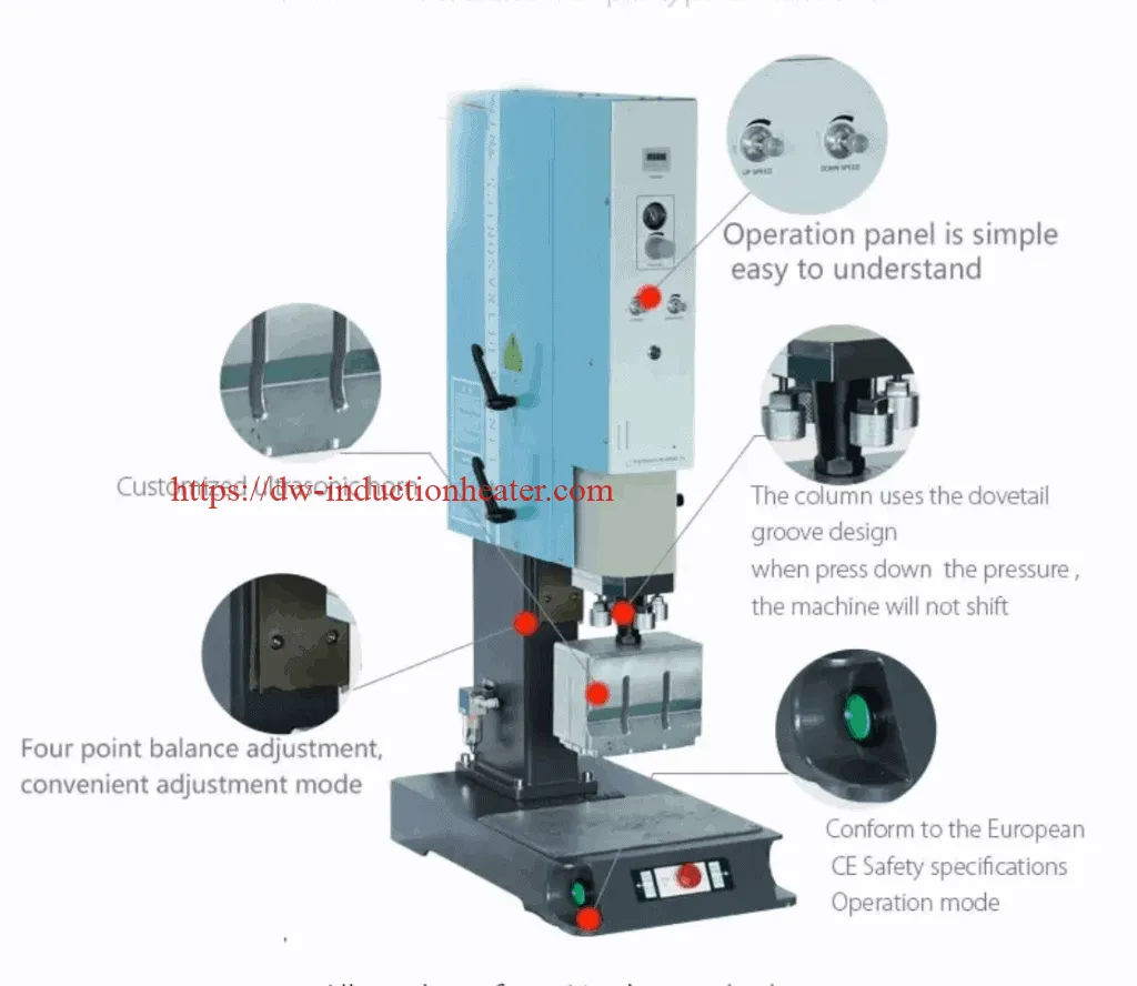 Main Features
1. Ultrasonic Welding Plastic Machine, manually tuning, simple to use and maintenance.
2. Welding by time, delay time, weld time and hold time. Working pressure is adjustable.
4. Precise and high quality imported pneumatic parts
5. High quality transducer and booster.
6. Self-protection: Over-Current, Frequency Deviation, Over-Temperature
7. Available in 4 frequencies – 15 KHz, 20 KHz ,35 KHz and 40 KHz.
8. Quick application changeover, high welding seam strength.
9. Suitable for high cadences and short cycle times.
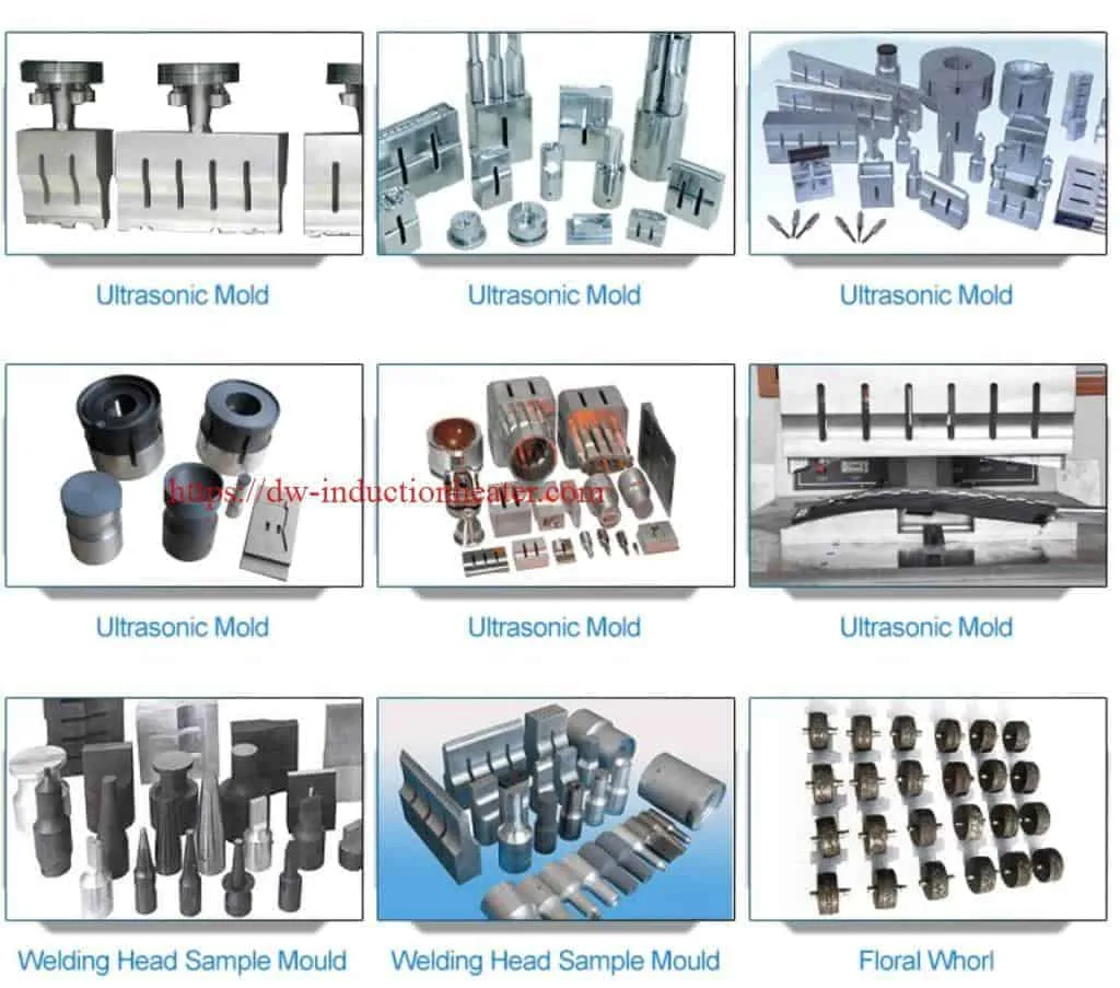
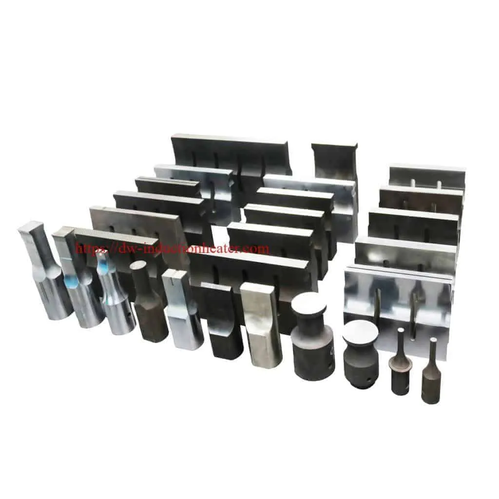
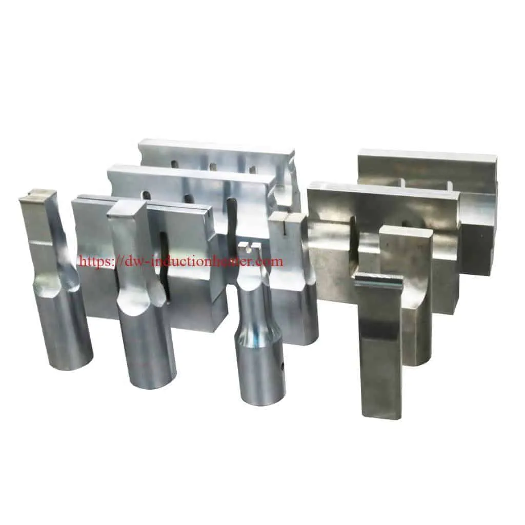
Ultrasonic Welding Horns/ultrasonic welding mold:
 Applications:
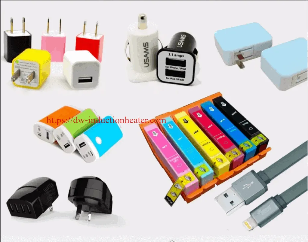
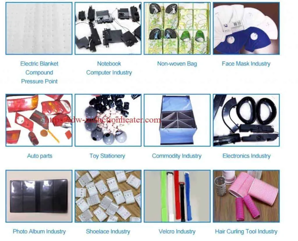
The applications of ultrasonic welding are extensive and are found in many industries including electrical and computer, automotive and aerospace, medical, and packaging. Whether two items can be ultrasonically welded is determined by their thickness. If they are too thick this process will not join them. This is the main obstacle in the welding of metals. However, wires, microcircuit connections, sheet metal, foils, ribbons and meshes are often joined using ultrasonic welding. Ultrasonic welding is a very popular technique for bonding thermoplastics. It is fast and easily automated with weld times often below one second and there is no ventilation system required to remove heat or exhaust. This type of welding is often used to build assemblies that are too small, too complex, or too delicate for more common welding techniques.
Automotive industry: plastic body parts, car doors, automotive dashboard, lights, mirrors, sun visor, interior parts, filters, reflective material, reflective spike, bumper, cable, plastic filter for motorcycle , Radiator, brake fluid tank, oil cups, water tanks, fuel tank, air hose, exhaust purifiers, the tray plate, and so on.
Plastic Electronics: prepaid water meters, communications equipment, cordless phones, mobile phone accessories, cell phone case, battery case, charger, maintenance valve regulated lead-acid batteries, 3-inch floppy disk, U disk, SD card, CF card, USB connection, Bluetooth devices, and so on.
Stationery: folder, album, folding boxes, PP hollow board, pen loops, ink cartridges, toner cartridges, and so on.
Medical and Daily products: watches, kitchen utensils, oral liquid bottle caps, drip caps, mobile phone accessories, golden soft brush, and daily necessities, handle, security caps, cosmetics bottle, coffee pot, washing machines, air dehumidifiers, Electric irons, electric kettles, vacuum cleaners, speakers, cover and metal face grille and other civil engineering and so on.
Health products: children's products, air mattresses, clothes hangers, gardening supplies, kitchenware sanitary ware, shower, shower head, and so on.

 [wpforms id="3947"]
2022年9月28日星期三
Induction Brazing & Soldering Principle
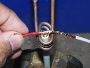
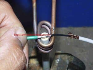
Induction Soldering Wire of Co-axial
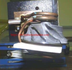
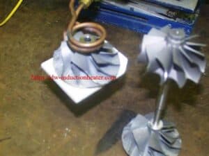
Induction Shrink Fit Aluminum Shaft
PDF of Induction Heating Principle and Applicatons
Induction Heating Principle and Applications PDF download for Research
Electromagnetic induction, simply induction, is a heating technique for electrical conductive materials (metals). Induction heating is frequently applied in several thermal processes such as the melting and the heating of metals. Induction heating has the important characteristic that the heat is generated in the material to be heated itself. Because of this, induction has a number of intrinsic trumps, such as a very quickheated itself. Because of this, induction has a number of intrinsic trumps, such as a very quick response and a good efficiency. Induction heating also allows heating very locally. Tare extremely high because of the high power density..... [caption id="attachment_5482" align="alignnone" width="1024"]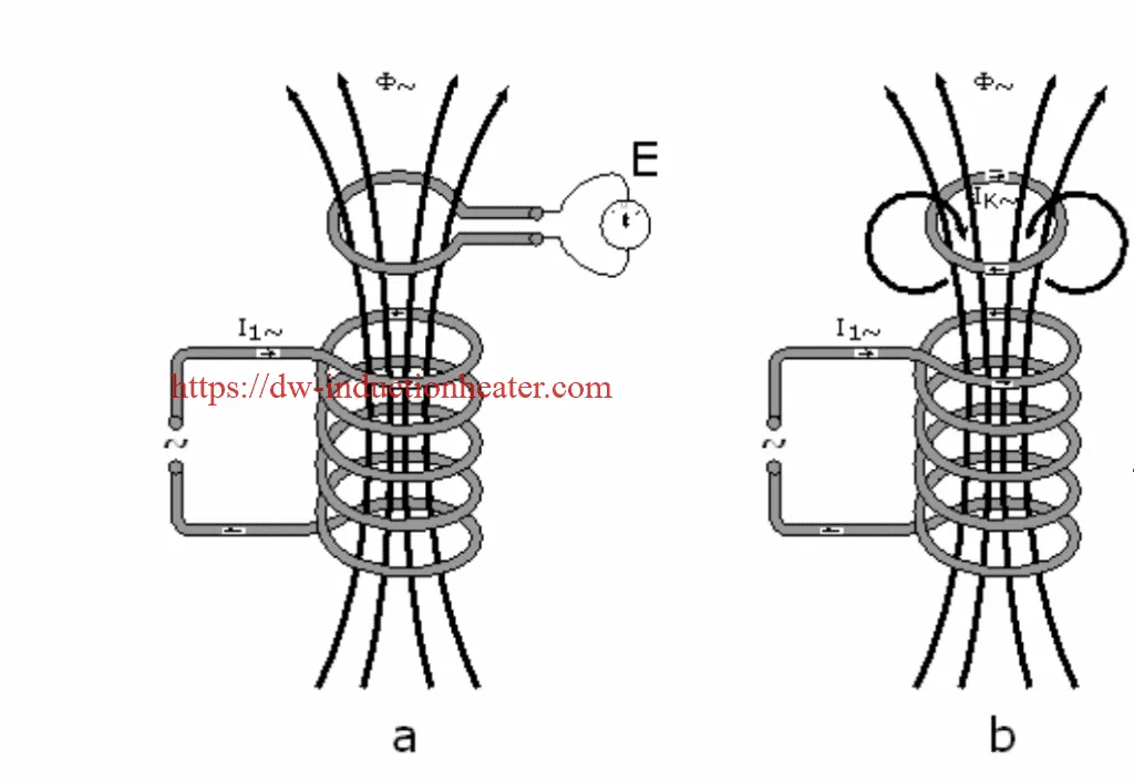 induction heating principle and applications[/caption]
induction_heating_principle_and_applications
induction preheating copper rod for hot forging
Induction preheating copper rod for hot forging
In order to want to improve safety and productivity, and reduce energy costs, by using induction instead of resistive heating. To maximize productivity, they want to be able to heat 3 brass rods at a time to 780° C within 25 seconds. For this application test, we are only heating one rod, so our goal is to heat the single rod to 780° C within 25 seconds with less than 45 kW of power. This will ensure that when heating 3 rods, that the 110 kW system will meet the production requirements.
Equipment DW-HF-70kW Induction Heating Power Supply, operating between 10-50 kHz
Materials • Brass rod • Custom coil, 10 turns, D=50mm, designed and manufactured by DaWei Induction Power Technologies for this specific application – capable to heat 3 rods at a heat cycle.
Key Parameters Temperature: 780° C Power: 70 kW Voltage: 380 – 480 V Time: 24 sec Frequency: 32 kHz
Process:
- The DW-HF series Power Supply was connected to the DW-HF-70kw Heat Station.
- The custom Coil was attached to the Heat Station.
- The Brass rods were placed inside the Coil.
- The Power Supply was turned on.
- The DW-HF series operating at 20 kW was able to successfully heat the single brass rod within 24 seconds, which was less than the 25 second time requirement established for the test. Three brass rods are expected then to heat within 25 seconds with approximately 60 kW of power (3 rods will be 3x the load and 3x the power). The 90 kW Induction system will therefore meet the customer’s requirements.
Results/Benefits:
Induction preheating provides:
- Faster heating cycles
- The process is safer than the flame heating
- Technology without pollution, clean and safe
induction preheating copper rod
high frequency induction preheating copper rod and connector for an epoxy curing application
induction preheating copper rod and connector for an epoxy curing application Objective: To preheat a portion of the copper rod and a rectangular connector to temperature prior to epoxy curing during a manufacturing process for electrical turnbuckles Material : Customer supplied plated copper rod (12” x 2” x 1”/305mm x 51mm x 102 mm) and connector Temperature :302 ºF (150 ºC) Frequency :25 kHz Induction Heating Equipment: -DW-HF-60kW 15-45 kHz induction heating system equipped with a remote workhead containing four 21 μF capacitors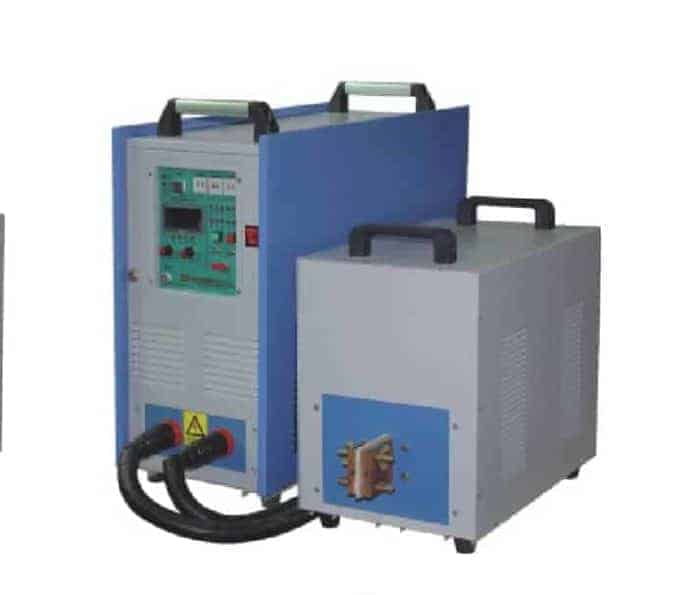 - A single position seven-turn helical induction heating coil designed and developed specifically for this application
Induction Heating Process
The copper rod and connector were placed inside the induction heating coil and the power was turned on. The part heated to temperature within 55 seconds. After being heated to temperature, the part was moved and an epoxy curing/molding process took place. The client was using a large oven to preheat these rods, which
was cost inefficient. Induction offers a faster and more costefficient heating method.
Results/Benefits - Speed: Induction heated the part to temperature quickly
- Efficiency: Induction is a far more efficient method of heating these parts to temperature when compared to their
large oven
- Precision: Induction made it possible to heat only the parts of the rod that required heating
关注者
博客归档
-
▼
2022
(1729)
-
▼
九月
(177)
- Induction Soldering Aluminum Housing
- Aluminum Tubes Induction Brazing
- Induction Brazing Principle-Theory
- Induction Handheld Brazing Copper To Steel Tube
- Induction Heating Solutions For Cancer Research
- Induction Bending Pipe-Tube
- Induction Brazing Machine
- induction Brazing copper rods to brass strips
- Handheld Induction Brazing HVAC Pipes of Heat Exch...
- Induction Soldering Brass Rings
- induction brazing steel tube to copper tube
- Ultrasonic Plastic Welding Machine For Bonding The...
- Induction Brazing & Soldering Principle
- Induction Soldering Wire of Co-axial
- Induction Shrink Fit Aluminum Shaft
- PDF of Induction Heating Principle and Applicatons
- induction preheating copper rod for hot forging
- induction preheating copper rod
- PDF of Induction Heating Principle and Applicatons
- Induction Brazing Stainless Steel
- Induction forging and induction hot forming
- Brazing Brass To Copper With Induction
- Induction Fluid Pipeline heating system
- High Frequency Induction Brazing Copper Wire
- induction surface hardening steel screws
- High Speed Heating by Induction Heating System
- Induction Soldering Brass Heating Exchanger
- Induction Brazing Copper Tube For Refrigeration
- Induction Brazing Machine
- Induction Wire Heating Process Applications
- Induction Preheat Welding Systems
- induction preheating titanium billet for rolling
- Induction Hot Plate
- Induction Annealing Aluminum PIpe
- Induction Heating Solutions For Cancer Research
- Induction Melting Videos
- Induction Soldering Aluminum Housing
- RPR Induction Stripping-Induction Rust & Paint Coa...
- Induction Brazing Carbide To Steel
- Heating Aluminum Foil For Cap Sealing
- induction heating stainless steel wire cable
- Brazing Eyeglass Frames With Induction
- refrigeration induction brazing refrigerator coppe...
- High Frequency Induction Brazing Copper Wire
- Induction Heating Plasma
- Induction Heating Solutions For Cancer Research
- Induction Brazing Carbide To Stainless Steel
- Induction Soldering Wire To Aluminum Lug
- Induction annealing stainless steel wire
- Technology of Induction Forming Steel Plate
- Brazing Carbide Tool Tips With Induction
- Brazing Copper Tube to Brass Fitting With Induction
- Heating Aluminum Foil For Cap Sealing
- Annealing Saw Blades with Induction
- induction heating diffusion pump with electromagne...
- hot water boiler with induction heating
- Induction inline wire heating process
- portable ultrasonic mask welding machine for weldi...
- Induction Shrink Fit Aluminum Shaft
- Induction Preheating Hot Rod Heading
- Induction Brazing Carbide Onto Steel Part
- How to design induction heating coil
- RPR Induction Stripping-Induction Rust & Paint Coa...
- induction brazing steel tube to copper tube
- Induction Soldering Brass Rings
- induction hardening process
- Induction straightening deck and bulkhead heating ...
- Induction Shrink Fit Aluminum Shaft
- what is induction forging?
- Induction Soldering Cables to Terminals
- Applications and Advantages of Induction Heating S...
- Induction Brazing Steel Parts to Tungsten Carbide ...
- Induction Brazing Brass Studs to Copper Pipes
- What is induction bonding?
- induction preheating copper bars
- Induction Soldering Brass Rings
- What Is Induction Heating?
- Induction Curing Heating of Organic Coating
- induction soldering fiber optic cable
- Induction Heating Steel Part For Hot Heading
- Brazing Stainless Steel To Copper With Induction
- Inductioin Shrink Fitting Aluminum Pulley
- Induction Soldering Steel Cover
- How Induction Heating works?
- What is Induction Brazing?
- induction heating graphite susceptor
- Applications and Advantages of Induction Heating S...
- What Is Induction Heating?
- Handheld Brazing Stainless Steel Tube
- Induction Wire Heating Process Applications
- Induction stress relieving flat blanks
- Induction Heat Treating Surface Process
- Induction Soldering Stainless Steel To Wire
- Induction Soldering Circuit Board
- induction heating for drying food processing industry
- Brazing Carbide To Steel Shank
- Induction Heating Steel Mold
- induction brazing carbide tip onto steel head teeth
- induction curing
- Induction Brazing Heating Exchanger Copper Pipes
-
▼
九月
(177)
我的简介

- HLQ induction heating machine
- HLQ induction heating machine manufacturer provides the service of induction brazing,melting,hot forming,hardening surface,annealing,shrink fitting,PWHT,etc.

