2024年3月31日星期日

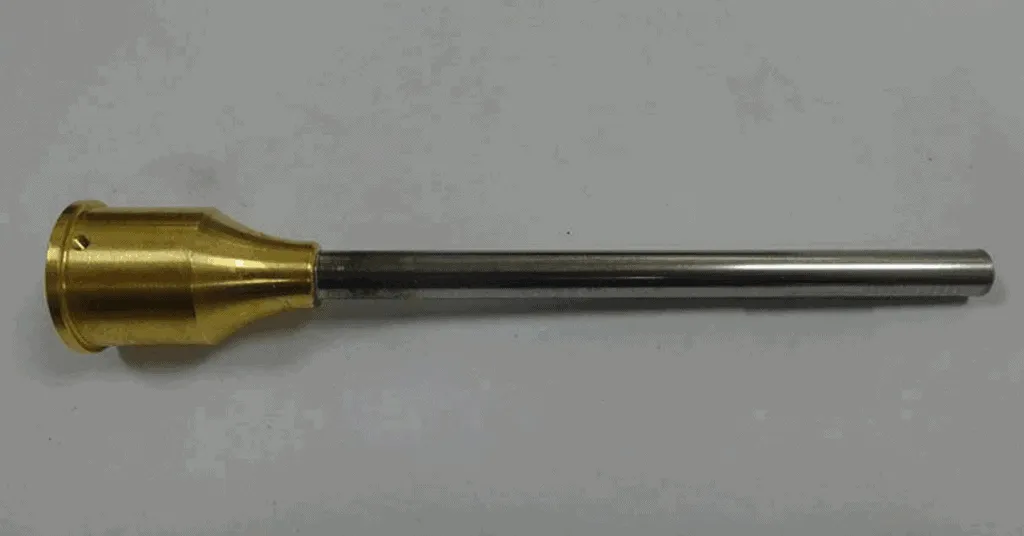
Induction Soldering Stainless Steel Tubes to Brass Base

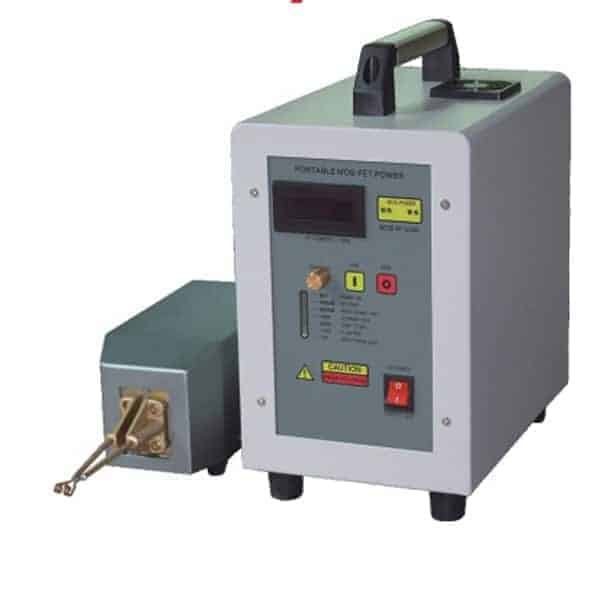
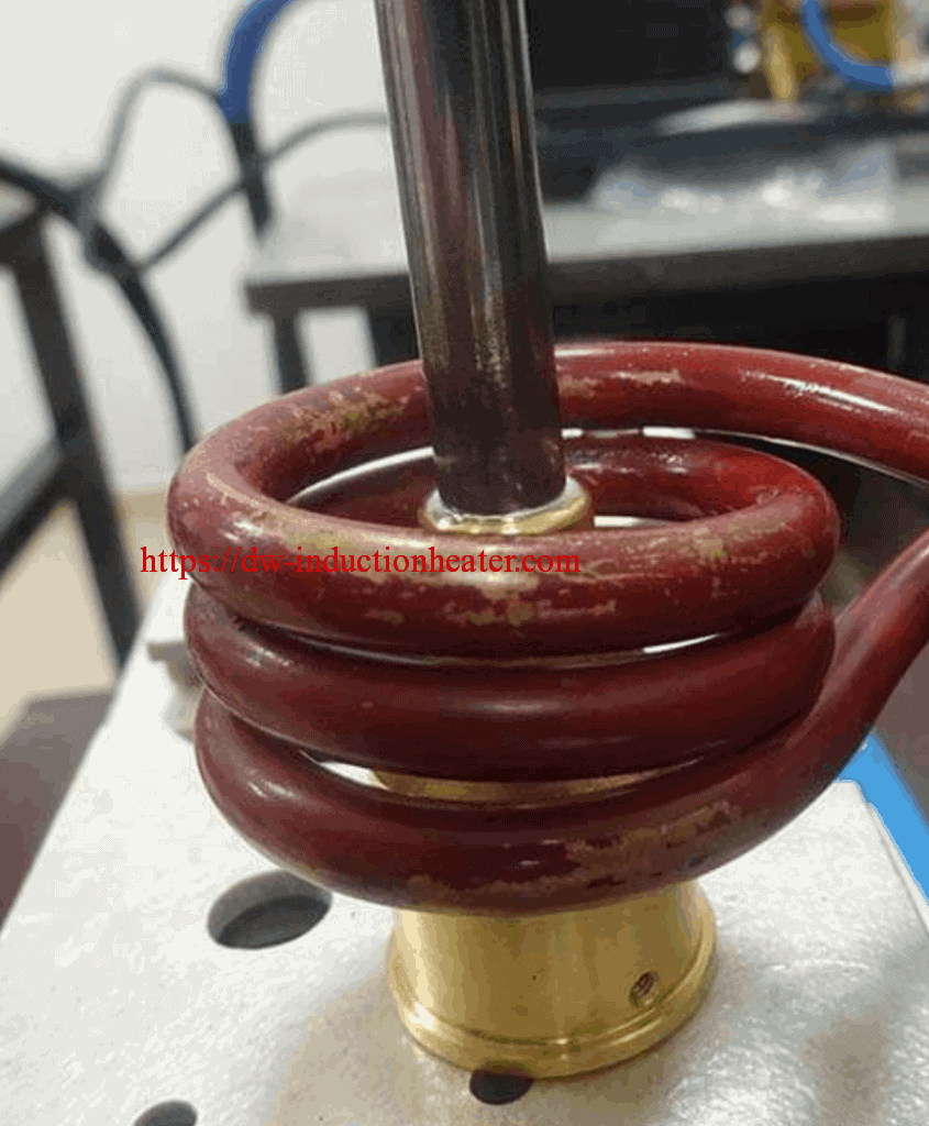
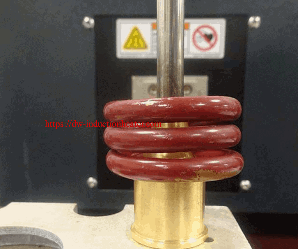
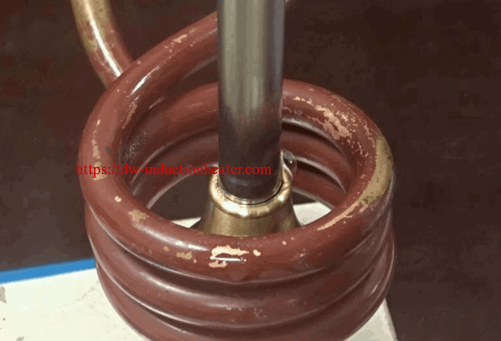
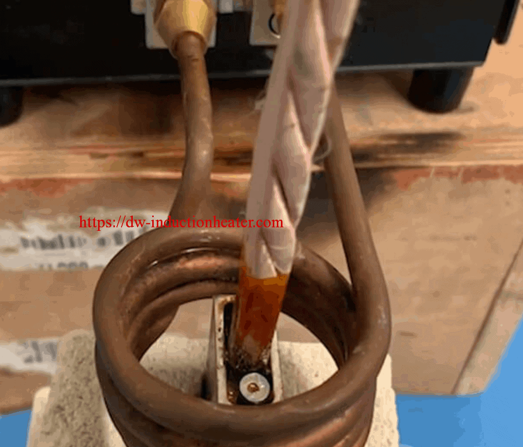
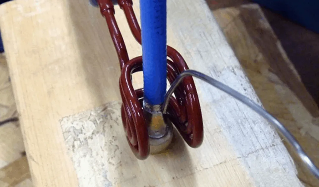
Objective Induction Soldering stainless steel tubes to brass base Equipment DW-UHF-6KW-III handheld induction heater
Materials Customer material including flux Key Parameters Power: 2 kW Temperature: 482°F (250°C not measured) Time: 14 -16 sec
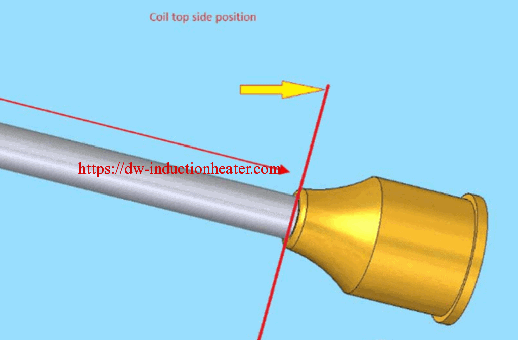
Process Steps Customer process instruction has been followed DW-UHF-6KW-III induction heating system was limited to 2kW Results and Conclusions Sample position according to the coil is vital.Induction Soldering Stainless steel is heated much fasted than the brass. So, the coil is positioned over the brass part (around 95%)
https://dw-inductionheater.com/induction-soldering-stainless-steel-tubes-to-brass-base.html?feed_id=239460&_unique_id=660a09f1c983d

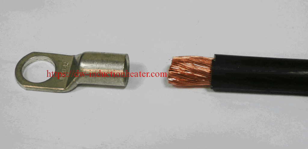
Induction Soldering Wire To Aluminum Lug

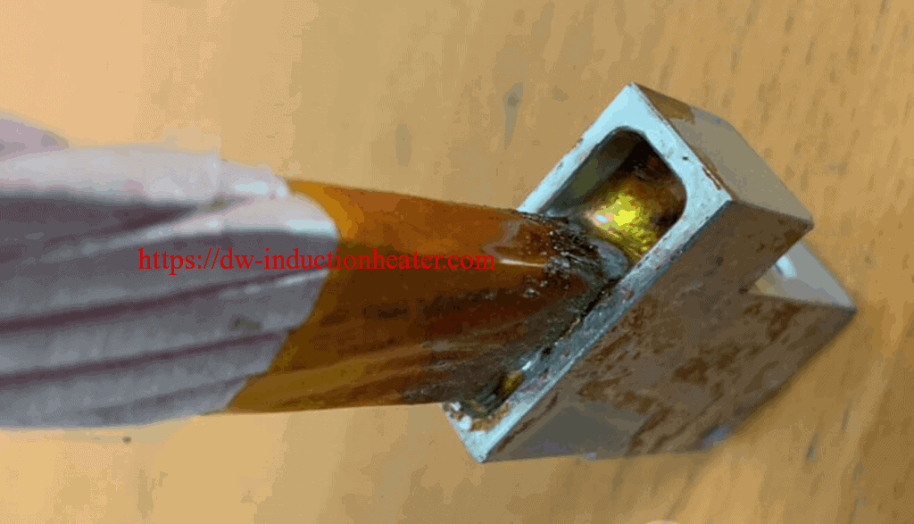
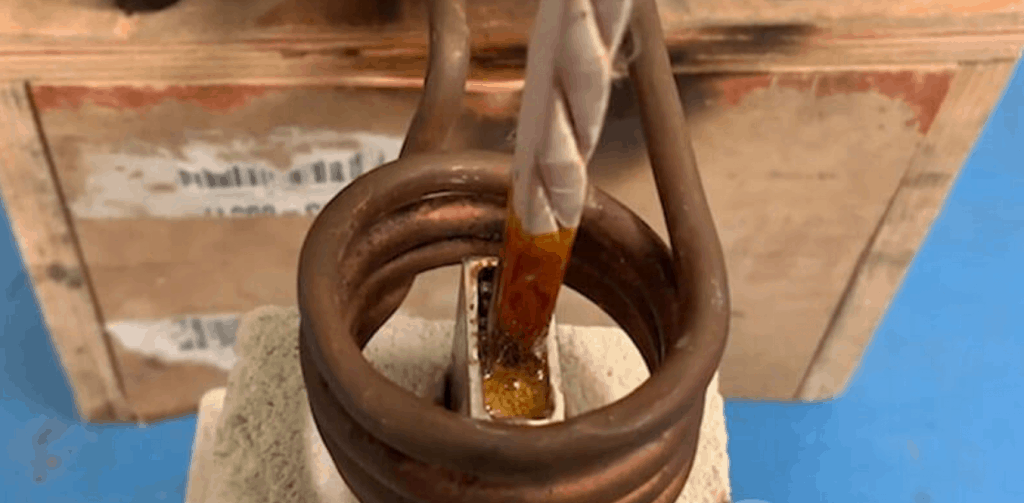
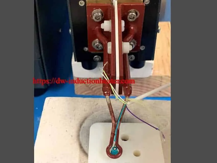
Objective The objective of this induction soldering wire to aluminum lug in under 30 seconds. Equipment DW-UHF-6KW-III handheld induction soldering heater HLQ custom coil Key Parameters Power: 1.75 kW Temperature: Approximately 250°C (482°F) Time: 25 seconds
Materials Aluminum Lug Litz Cables
Induction Soldering Process: In order to start the induction soldering process, the aluminum lug was placed in the center of the coil. Then the litz wire was placed into the lug along with the solder. The solder started to melt after 25 seconds at approximately 250°C (482°F). After the solder was completely melted it was left to cool for one minute before proceeding.
Results: The tests were a success. We were able to prove that induction heating was a much faster method of induction soldering wire to aluminum lug rather than using a torch as the customer had done in the past. The application testing showed an increase in productivity and control over the time and temperature.
https://dw-inductionheater.com/induction-soldering-wire-to-aluminum-lug.html?feed_id=239392&_unique_id=660953289f1ad

2024年3月30日星期六

high frequency induction soldering wire to connector

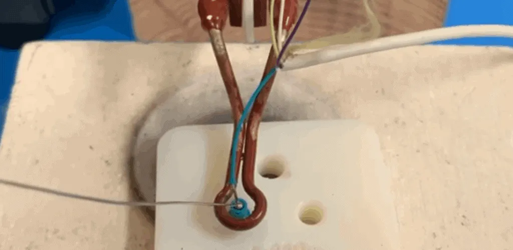
Objective The purpose of this test is to demonstrate the induction soldering wire to connector Recommended Equipment The recommended equipment for this test is the with the customized induction heating coil.  DW-UHF-6KW-I handheld induction heater
Key Parameters Power: Up to 0.48 kW Temperature: 392°F (200°C) Time: 1.5 seconds
Process and Results: This induction soldering wire to connector process was quick yet effective. The unit was run at 985 kHz, the reason for using such a high frequency was to couple into the small diameter of the wires. The whole process from the heat being turned on to the hardening of the solder took 1.5 seconds. Previously a soldering iron was being used to complete this task, however induction soldering was proven to be much faster and more efficient. The process can now be automated on an assembly line, because the system can remotely be turned on.
https://dw-inductionheater.com/high-frequency-induction-soldering-wire-to-connector.html?feed_id=239324&_unique_id=66089c76922a3

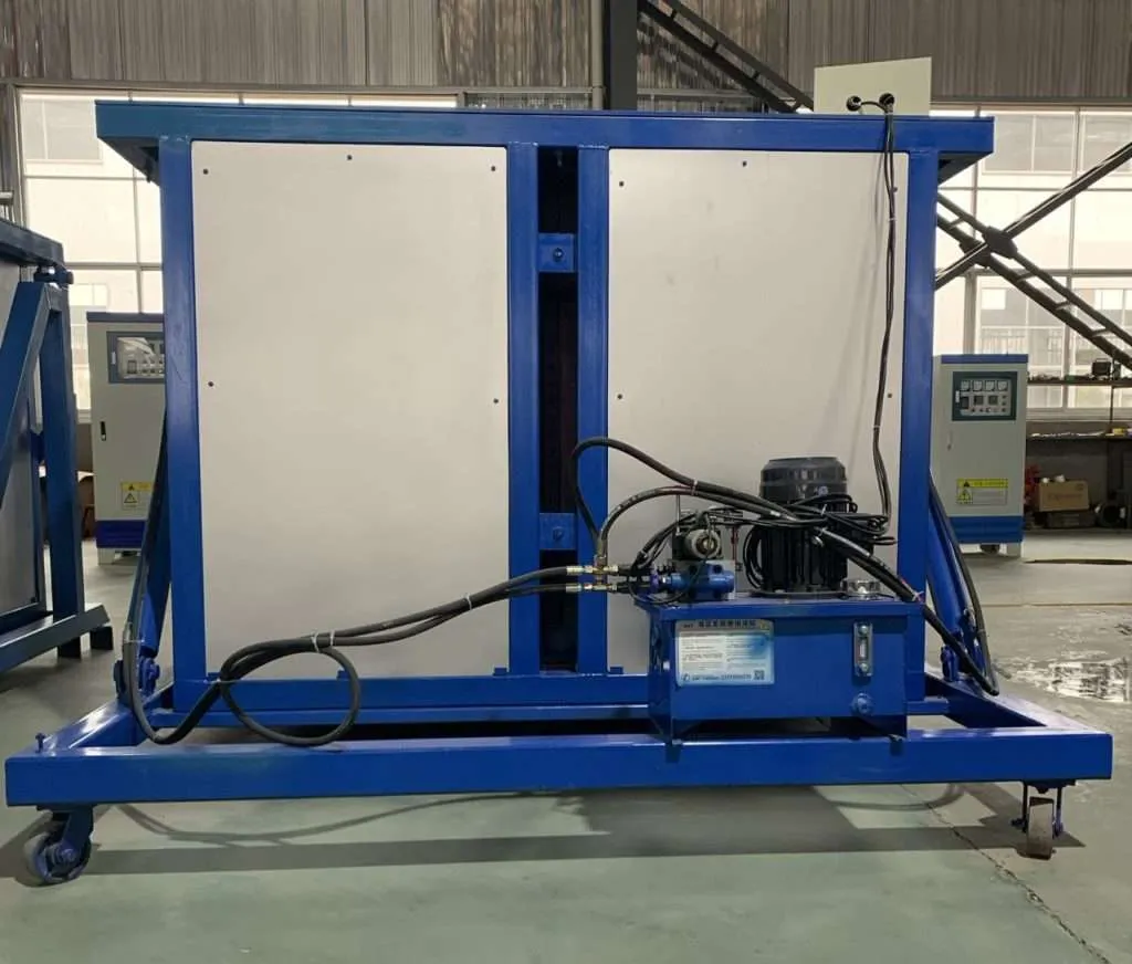
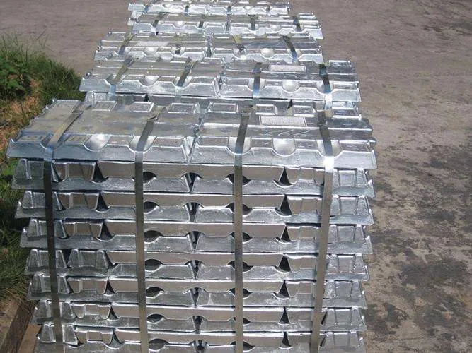
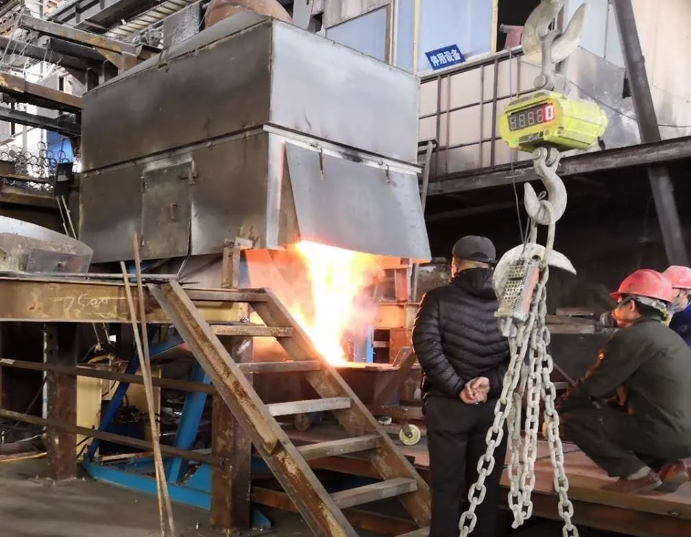
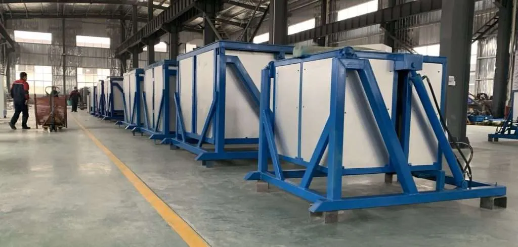
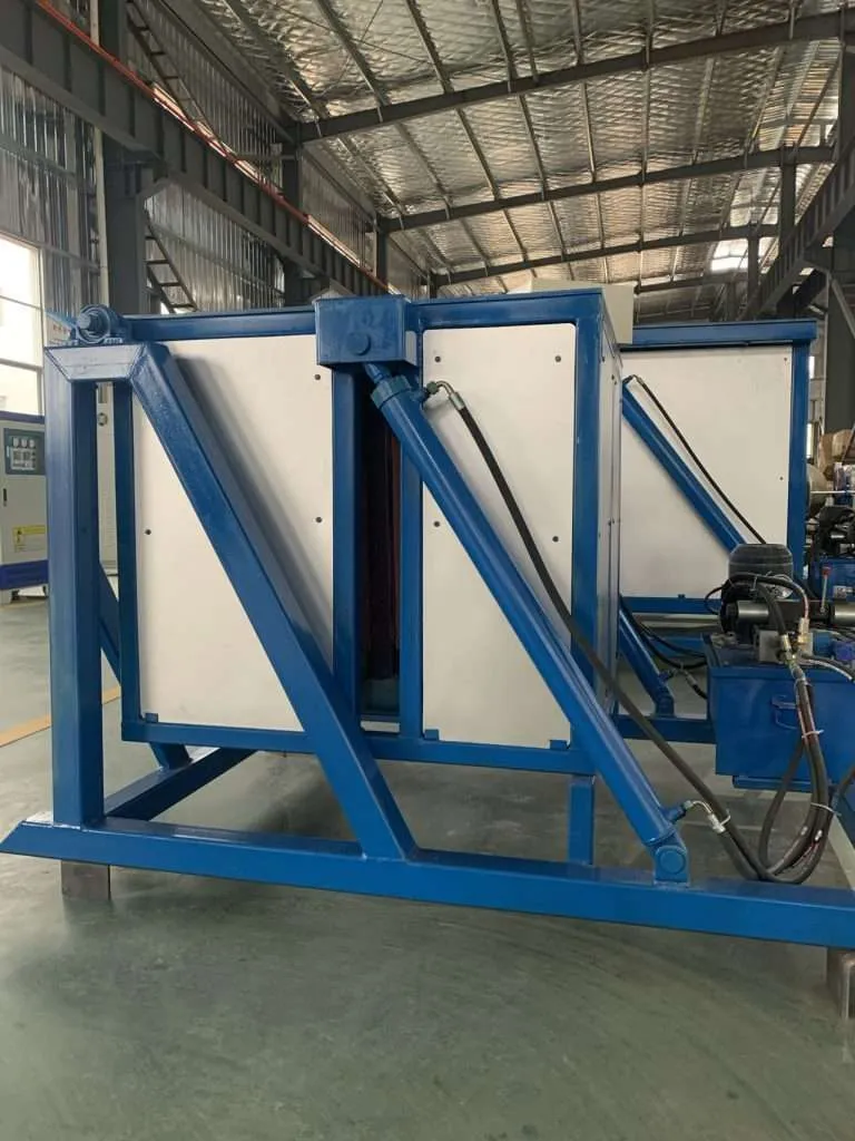
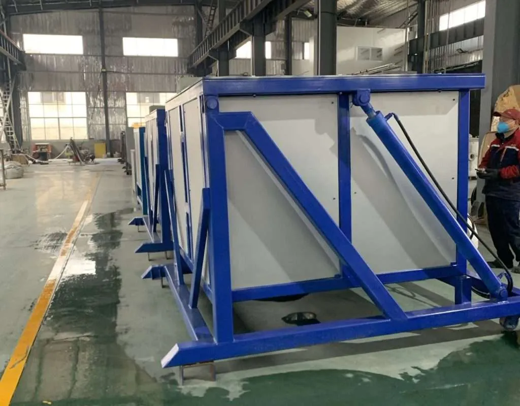
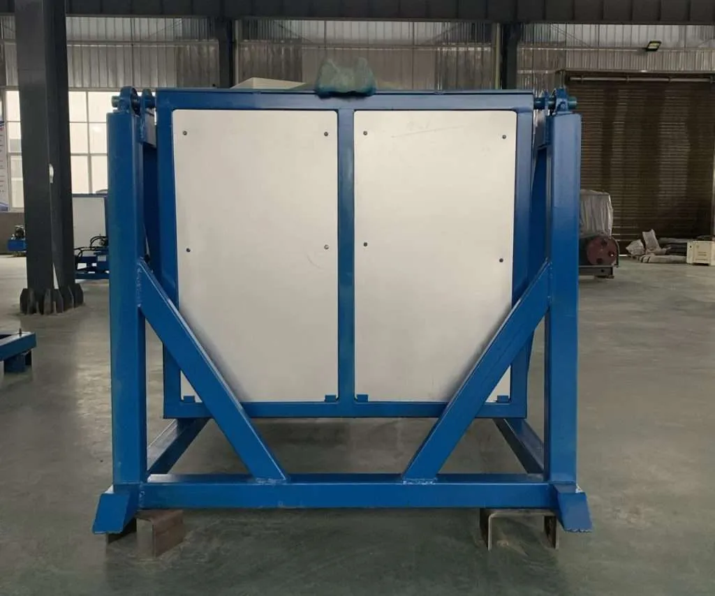
Induction Zinc Alloy Melting Furnace-Zinc Smelting Oven Manufacturer

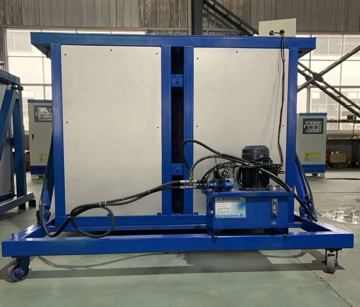
Induction Zinc Alloy Melting Furnace: The Efficient Solution for Metalworking In the ever-evolving world of metalworking, efficiency and precision are paramount. Whether you're a small-scale manufacturer or a large-scale production facility, having the right equipment can make all the difference. One such crucial piece of machinery is the induction zinc alloy melting furnace. This advanced technology has revolutionized the way zinc alloys are melted, casting, and processed, offering unparalleled benefits that set it apart from traditional melting methods. What is an Induction Zinc Alloy Melting Furnace? An induction zinc alloy melting furnace is a specialized piece of equipment designed to melt and maintain the molten state of zinc alloys using the principle of electromagnetic induction. Unlike conventional furnaces that rely on direct heat transfer through combustion or resistance heating, induction furnaces generate heat within the metal itself. How Does an Induction Zinc Alloy Melting Furnace Work? The process of melting zinc alloys in an induction furnace is based on the principle of electromagnetic induction. Here's how it works:
  1. Induction Coil: At the heart of the furnace lies an induction coil, typically made of copper tubing. This coil is connected to a high-frequency alternating current (AC) power supply.
  2. Alternating Magnetic Field: When the AC current flows through the induction coil, it creates an alternating magnetic field within the furnace chamber.
  3. Eddy Currents: As the zinc alloy charge is placed inside the furnace chamber, the alternating magnetic field induces eddy currents within the metal itself.
  4. Joule Heating: These eddy currents encounter resistance as they flow through the metal, resulting in the generation of heat due to the Joule heating effect. The heat is distributed evenly throughout the metal, causing it to melt from within.
  5. Melting and Holding: The induction furnace can precisely control the temperature and melt rate, ensuring consistent and efficient melting of the zinc alloy. Once melted, the furnace can maintain the molten state of the metal for as long as needed.
Advantages of Induction Zinc Alloy Melting Furnaces Energy Efficiency: Induction furnaces are highly energy-efficient compared to traditional melting methods. Since the heat is generated within the metal itself, there is minimal energy loss, resulting in significant cost savings and reduced environmental impact. Precise Temperature Control: The temperature of the molten metal can be accurately controlled and maintained, ensuring consistent quality and minimizing the risk of overheating or underheating. Clean Melting Process: Induction furnaces operate in a closed system, minimizing exposure to atmospheric contaminants and reducing the risk of oxidation or other chemical reactions that can affect the quality of the molten metal. Fast Melting Rates: Induction furnaces can melt zinc alloys at a much faster rate compared to conventional furnaces, increasing productivity and reducing overall processing times. Versatility: Induction furnaces can handle a wide range of zinc alloy compositions, making them suitable for various applications in the metalworking industry. Applications of Induction Zinc Alloy Melting Furnaces Induction zinc alloy melting furnaces find applications in numerous industries, including:
  1. Die Casting: Zinc alloys are widely used in the die casting industry for producing intricate and high-precision components for various sectors, such as automotive, electronics, and consumer goods.
  2. Foundry Operations: Induction furnaces are employed in foundries for melting and casting zinc alloys into various shapes and sizes, catering to diverse industrial needs.
  3. Galvanizing: Zinc alloys play a crucial role in the galvanizing process, where steel or iron components are coated with a protective zinc layer to prevent corrosion. Induction furnaces ensure consistent and efficient melting of the zinc alloy for this process.
  4. Alloy Development: The precise temperature control and clean melting environment offered by induction furnaces make them ideal for developing and testing new zinc alloy compositions.
Choosing the Right Induction Zinc Alloy Melting Furnace When selecting an induction zinc alloy melting furnace, several factors must be considered:
  1. Capacity: Determine the required melting capacity based on your production needs and the volume of zinc alloy to be processed.
  2. Power Requirements: Assess the available power supply and choose a furnace that meets your electrical requirements while ensuring efficient operation.
  3. Temperature Range: Ensure that the furnace can achieve and maintain the desired temperature range for melting and holding the specific zinc alloy composition.
  4. Automation and Control: Consider the level of automation and control features required for your production process, such as programmable temperature profiles, data logging, and remote monitoring capabilities.
  5. Safety Features: Prioritize furnaces with robust safety features, including emergency shutdown systems, overheating protection, and proper insulation and shielding.
  6. Maintenance and Support: Evaluate the manufacturer's reputation, availability of spare parts, and technical support services to ensure reliable and long-term operation.
  7. What types of zinc alloys can be melted in an induction furnace? Induction furnaces are versatile and can be used to melt a wide variety of zinc alloys including die-casting alloys like Zamak, as well as other specialized zinc-based alloys used in different industries. The high frequency used in induction furnaces is suitable for achieving the melting points of these various alloys without contaminating the metal, unlike some other furnaces that may use contact methods of heating.
  8. How do you maintain an induction zinc alloy melting furnace? Regular maintenance is crucial for ensuring the furnace operates efficiently and has a long service life. Maintenance tasks may include:
    • Checking and Tightening Connections: Regularly inspecting and ensuring that electrical connections are tight to avoid power losses and potential dangers.
    • Cooling System Maintenance: Keeping the cooling system in good working order, which often involves checking for leaks and ensuring that the coolant is at the correct level and condition.
    • Coil Inspection: The induction coil should be inspected for cracks or wear since it is a critical component of the furnace.
    • Cleaning: Regularly remove any accumulated debris or metal spillage to prevent damage and inefficiency.
    • Professional Inspections: Have qualified technicians perform periodic inspections and calibrations to ensure everything is working correctly and to troubleshoot any potential issues.
  9. What safety measures should be observed when operating an induction zinc alloy melting furnace?
    • Proper Training: Only trained personnel should operate the furnace.
    • Personal Protective Equipment (PPE): Operators should wear appropriate PPE, such as heat-resistant gloves, safety goggles, and protective clothing.
    • Emergency Procedures: Establish and practice clear emergency procedures for dealing with incidents such as molten metal spillage or electrical faults.
    • Regular Checks: Implement regular checks of the furnace's safety features, such as emergency stop buttons, safety interlocks, and temperature controls.
    • Ventilation: Ensure the facility is well-ventilated to prevent the buildup of fumes that can be hazardous when metals are melted.
Conclusion The induction zinc alloy melting furnace has emerged as a game-changer in the metalworking industry, offering unparalleled efficiency, precision, and versatility. With its energy-saving capabilities, clean melting process, and precise temperature control, this technology has become an indispensable tool for manufacturers seeking to optimize their production processes and meet the highest quality standards. Whether you're involved in die casting, foundry operations, galvanizing, or alloy development, investing in a reliable induction zinc alloy melting furnace can provide a significant competitive edge and ensure consistent, high-quality results.
 
https://dw-inductionheater.com/product/induction-zinc-alloy-melting-furnace-zinc-smelting-oven-manufacturer?feed_id=239290&_unique_id=66081162e7fa7

Induction Soldering Brass to Steel Plate

High Frequency Induction Soldering Brass to Steel Plate Technology

Objective High Frequency Induction Soldering brass to steel plate Equipment DW-UHF-6KW-I handheld induction brazing heater
Materials Steel plate to brass part induction soldering using Harris Stay-Brite #8 Silver Bearing Solder and Harris Bridgit Lead Free Soldering Flux. Key Parameters Power: 2kW Temperature: 535°F to 585°F (279°C to 307°C) Time: 21 Seconds  
https://dw-inductionheater.com/induction-soldering-brass-to-steel-plate.html?feed_id=239227&_unique_id=6607e5b4e654f

2024年3月29日星期五

Induction Soldering Cable to Metallic Plate

Objective The purpose of this test is to demonstrate the induction soldering cable to metallic plate process. Recommended Equipment The recommended equipment for this test is the DW-UHF-6kw-I handheld induction heater.
Key Parameters Power: Up to 0.72 kW Temperature: 482°F (250°C) Time: 4.5 seconds to 14 seconds
Results and Conclusions: The results were satisfactory at 14 seconds. The complete process can be achieved in less than 5 seconds by increasing the frequency from under 200 kHz to over 300 kHz, as well as by increasing the induction heating power
https://dw-inductionheater.com/induction-soldering-cable-to-metallic-plate.html?feed_id=239159&_unique_id=66072ec213f44

Induction Soldering Cables to Terminals

Objective Induction Soldering cables to terminals in under 20 seconds using induction.
Equipment DW-UHF-6KW-I handheld induction heater Materials • 0.078″2 (50mm2) cable terminal • 0.078″2 (50mm2) cable • Soldering alloy Sn60Pb38Cu2 Key Parameters Power: 2.8 kW Time: 15-20 sec Temperature: 500° F (260° C)
Process:
  1. The 0.078″2 (50mm2) cable terminal is attached to 0.078″2 (50mm2) cable
  2. The assembly is positioned inside the coil and induction heating is applied.
  3. Time to temperature is about 4 -5 sec. The temperature is maintained constant to complete the soldering process. A foot switch is used to start and stop the machine.
  4. After 15-20 sec, the cable and cable terminal are successfully soldered.
Results/Benefits: Suitable induction heating systems for the process: DW-UHF-6KW-I handheld induction heater The DW-UHF-6KW-I handheld induction heater will require a longer time to reach temperature and complete soldering. Induction heating provides:
  • Strong durable joints
  • Selective and precise heat zone, resulting in less part distortion and joint stress
  • Less oxidation
  • Faster heating cycles
  • More consistent results and suitability for large volume production, without the need for batch processing
  • Technology without pollution, which is clean and safe
https://dw-inductionheater.com/induction-soldering-cables-to-terminals.html?feed_id=239091&_unique_id=660678285e759

2024年3月28日星期四

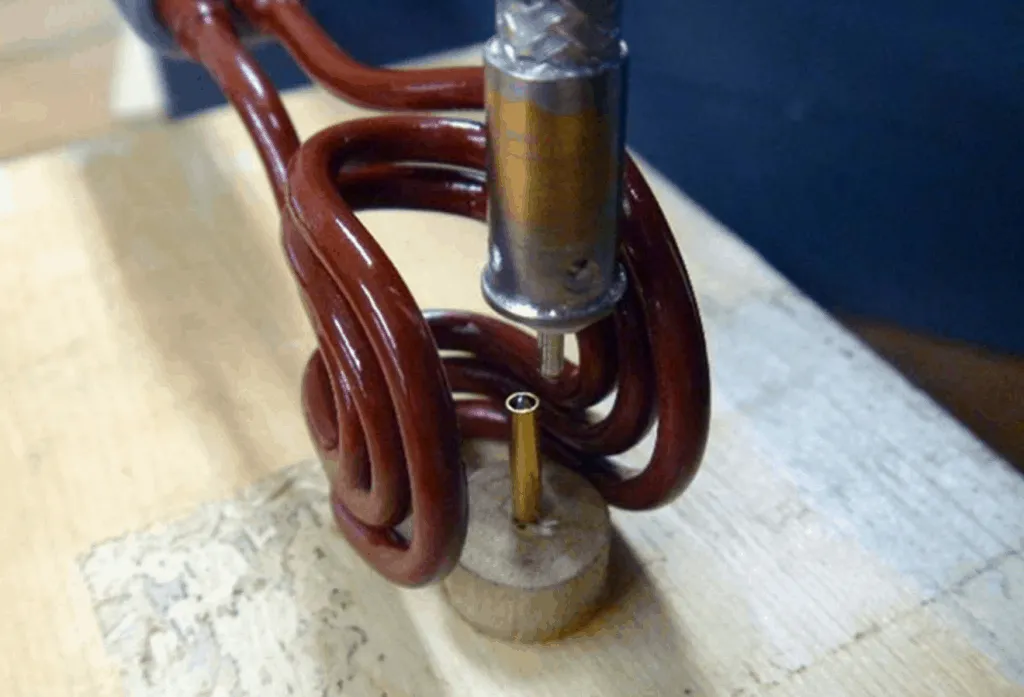
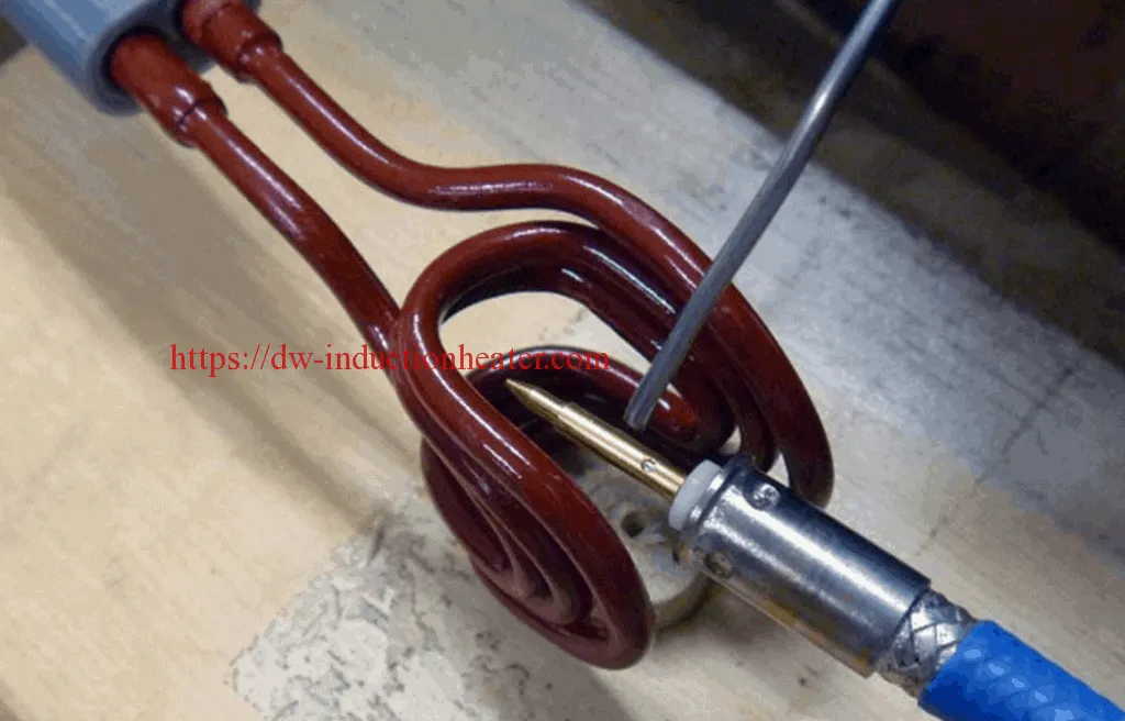
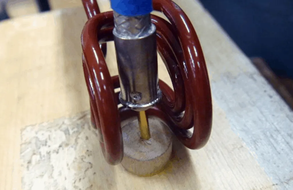
Induction Soldering Coaxial Cable to Connector Ring

Objective Induction Soldering coaxial cable to connector ring and pin in two steps in under 5 seconds by reaching a temperature of 500°F (260°C) with induction heating.
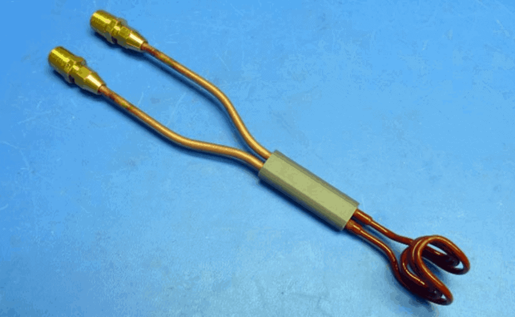
Equipment  DW-UHF-6KW-I handheld induction Soldering Heater Materials • No-flux solder wire • Coaxial cable • Cable connector • Center pin Key Parameters Power: 1.0kW Temperature: 662°F (350°C) Time: 5 sec
Process:
  1. The coaxial cable and connector were placed vertically inside the coil.
  2. Induction heating was applied for 3 seconds, at which point the part is hot enough for soldering.
  3. The soldering wire was fed between the cable braid and connector.
  4. Solder wire was inserted into the center pin, and the center pin was placed in the coil.
  5. The cable with connector was placed above the pin.
  6. Induction heating was applied for 1.5 seconds, after which the part was hot enough for soldering.
  7. The center conductor was inserted into the pin.
  8. The assembly was inspected to ensure that the induction soldering was successful.
Results/Benefits:
  • Strong durable joints and faster heating cycles
  • Selective and precise heat zone, resulting in less part distortion and joint stress
  • Technology without pollution, which is both clean and safe
 
https://dw-inductionheater.com/induction-soldering-coaxial-cable-to-connector-ring.html?feed_id=239023&_unique_id=6605c12449b39

Induction Hardening of Large-Diameter Shafts and Cylinders

Induction Hardening of Large-Diameter Shafts and Cylinders

Introduction
A. Definition of induction hardening

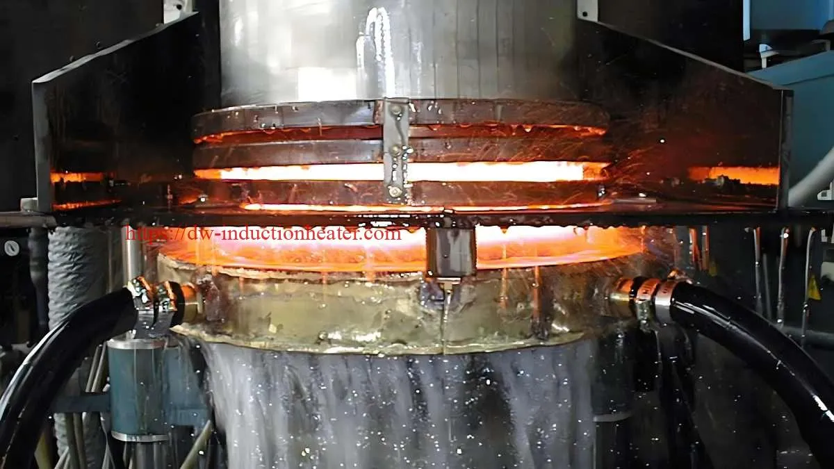
Induction hardening is a heat treatment process that selectively hardens the surface of metallic components using electromagnetic induction. It is widely employed in various industries to enhance the wear resistance, fatigue strength, and durability of critical components.

B. Importance for large-diameter components

Large-diameter shafts and cylinders are essential components in numerous applications, ranging from automotive and industrial machinery to hydraulic and pneumatic systems. These components are subjected to high stresses and wear during operation, necessitating a robust and durable surface. Induction hardening plays a crucial role in achieving the desired surface properties while maintaining the ductility and toughness of the core material. II. Principles of Induction Hardening

A. Heating mechanism

1. Electromagnetic induction

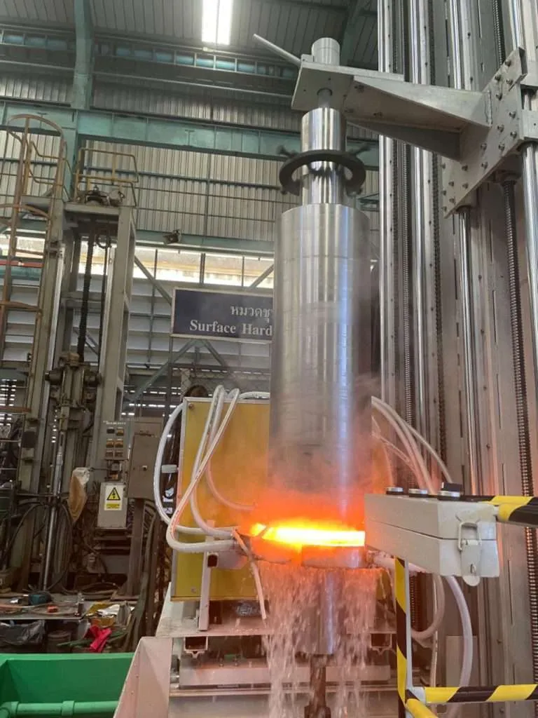
The induction hardening process relies on the principle of electromagnetic induction. An alternating current flows through a copper coil, creating a rapidly alternating magnetic field. When a electrically conductive workpiece is placed within this magnetic field, eddy currents are induced within the material, causing it to heat up.
2. Skin effect

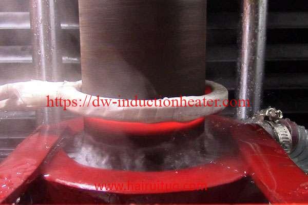
The skin effect is a phenomenon where the induced eddy currents are concentrated near the surface of the workpiece. This results in rapid heating of the surface layer while minimizing heat transfer to the core. The depth of the hardened case can be controlled by adjusting the induction frequency and power levels.

B. Heating pattern

1. Concentric rings

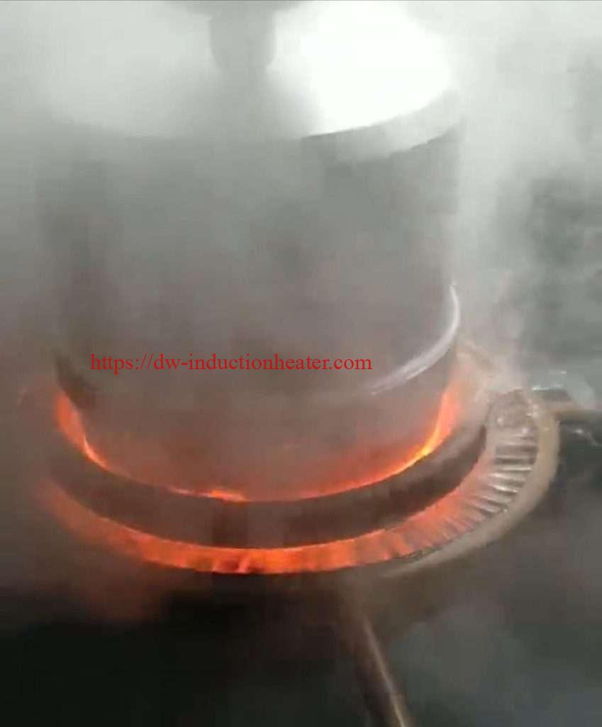
During induction hardening of large-diameter components, the heating pattern typically forms concentric rings on the surface. This is due to the distribution of the magnetic field and the resulting eddy current patterns.

2. End effects

At the ends of the workpiece, the magnetic field lines tend to diverge, leading to a non-uniform heating pattern known as the end effect. This phenomenon requires specific strategies to ensure consistent hardening throughout the component. III. Advantages of Induction Hardening

A. Selective hardening

One of the primary advantages of induction hardening is its ability to selectively harden specific areas of a component. This allows for the optimization of wear resistance and fatigue strength in critical regions while maintaining ductility and toughness in non-critical areas.
B. Minimal distortion

Compared to other heat treatment processes, induction hardening results in minimal distortion of the workpiece. This is because only the surface layer is heated, while the core remains relatively cool, minimizing thermal stresses and deformation.

C. Improved wear resistance

The hardened surface layer achieved through induction hardening significantly enhances the wear resistance of the component. This is particularly important for large-diameter shafts and cylinders that are subjected to high loads and friction during operation.

D. Increased fatigue strength

The compressive residual stresses induced by the rapid cooling during the induction hardening process can improve the fatigue strength of the component. This is crucial for applications where cyclic loading is a concern, such as in automotive and industrial machinery. IV. Induction Hardening Process

A. Equipment

1. Induction heating system

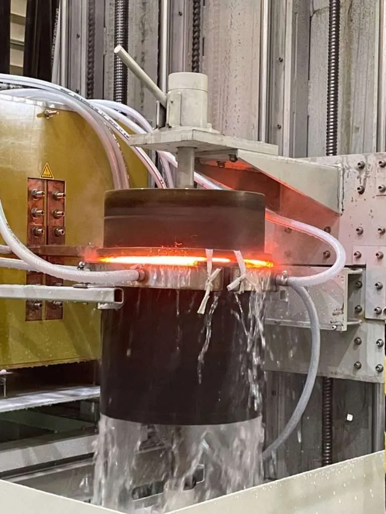
The induction heating system consists of a power supply, a high-frequency inverter, and an induction coil. The power supply provides the electrical energy, while the inverter converts it to the desired frequency. The induction coil, typically made of copper, generates the magnetic field that induces eddy currents in the workpiece.

2. Quenching system

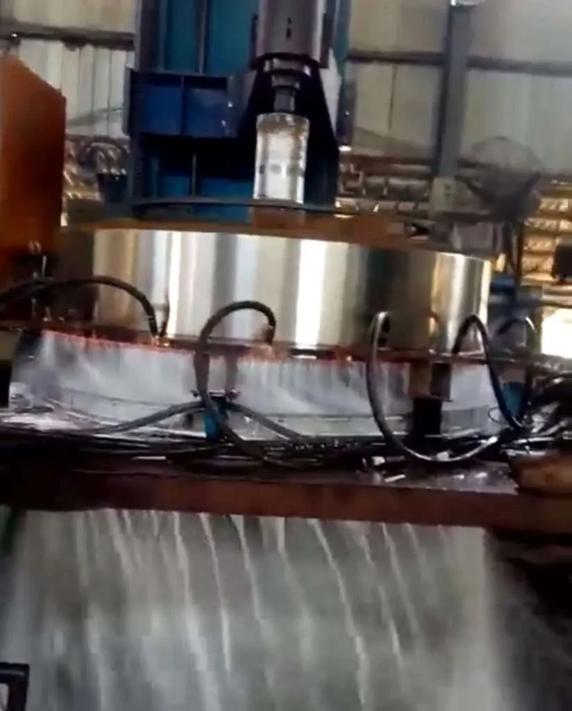
After the surface layer is heated to the desired temperature, rapid cooling (quenching) is necessary to achieve the desired microstructure and hardness. Quenching systems can utilize various media, such as water, polymer solutions, or gas (air or nitrogen), depending on the component's size and geometry.

B. Process parameters

1. Power

The power level of the induction heating system determines the rate of heating and the depth of the hardened case. Higher power levels result in faster heating rates and deeper case depths, while lower power levels provide better control and minimize potential distortion.
2. Frequency

The frequency of the alternating current in the induction coil influences the depth of the hardened case. Higher frequencies result in shallower case depths due to the skin effect, while lower frequencies penetrate deeper into the material.

3. Heating time

The heating time is crucial for achieving the desired temperature and microstructure in the surface layer. Precise control of the heating time is essential to prevent overheating or underheating, which can lead to undesirable properties or distortion.

4. Quenching method

The quenching method plays a vital role in determining the final microstructure and properties of the hardened surface. Factors such as quenching medium, flow rate, and uniformity of coverage must be carefully controlled to ensure consistent hardening throughout the component. V. Challenges with Large-Diameter Components

A. Temperature control

Achieving uniform temperature distribution across the surface of large-diameter components can be challenging. Temperature gradients can lead to inconsistent hardening and potential distortion or cracking.

B. Distortion management

Large-diameter components are more susceptible to distortion due to their size and the thermal stresses induced during the induction hardening process. Proper fixturing and process control are essential to minimize distortion.

C. Quenching uniformity

Ensuring uniform quenching across the entire surface of large-diameter components is crucial for achieving consistent hardening. Inadequate quenching can result in soft spots or uneven hardness distribution. VI. Strategies for Successful Hardening

A. Heating pattern optimization

Optimizing the heating pattern is essential for achieving uniform hardening on large-diameter components. This can be accomplished through careful coil design, adjustments to the induction frequency and power levels, and the use of specialized scanning techniques.

B. Induction coil design

The design of the induction coil plays a crucial role in controlling the heating pattern and ensuring uniform hardening. Factors such as coil geometry, turn density, and positioning relative to the workpiece must be carefully considered.

C. Quenching system selection

Selecting the appropriate quenching system is vital for successful hardening of large-diameter components. Factors such as quenching medium, flow rate, and coverage area must be evaluated based on the component's size, geometry, and material properties.

D. Process monitoring and control

Implementing robust process monitoring and control systems is essential for achieving consistent and repeatable results. Temperature sensors, hardness testing, and closed-loop feedback systems can help maintain process parameters within acceptable ranges.
VII. Applications

A. Shafts

1. Automotive

Induction hardening is widely used in the automotive industry for hardening large-diameter shafts in applications such as driveshafts, axles, and transmission components. These components require high wear resistance and fatigue strength to withstand the demanding operating conditions.

2. Industrial machinery

Large-diameter shafts are also commonly hardened using induction hardening in various industrial machinery applications, such as power transmission systems, rolling mills, and mining equipment. The hardened surface ensures reliable performance and extended service life under heavy loads and harsh environments.

B. Cylinders

1. Hydraulic

Hydraulic cylinders, particularly those with large diameters, benefit from induction hardening to improve wear resistance and extend service life. The hardened surface minimizes wear caused by high-pressure fluid and sliding contact with seals and pistons.

2. Pneumatic

Similar to hydraulic cylinders, large-diameter pneumatic cylinders used in various industrial applications can be induction hardened to enhance their durability and resistance to wear caused by compressed air and sliding components. VIII. Quality Control and Testing

A. Hardness testing

Hardness testing is a crucial quality control measure in induction hardening. Various methods, such as Rockwell, Vickers, or Brinell hardness testing, can be employed to ensure that the hardened surface meets the specified requirements.

B. Microstructural analysis

Metallographic examination and microstructural analysis can provide valuable insights into the quality of the hardened case. Techniques such as optical microscopy and scanning electron microscopy can be used to evaluate the microstructure, case depth, and potential defects.

C. Residual stress measurement

Measuring residual stresses in the hardened surface is important for assessing the potential for distortion and cracking. X-ray diffraction and other non-destructive techniques can be used to measure residual stresses and ensure they are within acceptable limits. IX. Conclusion

A. Summary of key points

Induction hardening is a crucial process for enhancing the surface properties of large-diameter shafts and cylinders. By selectively hardening the surface layer, this process improves wear resistance, fatigue strength, and durability while maintaining the ductility and toughness of the core material. Through careful control of process parameters, coil design, and quenching systems, consistent and repeatable results can be achieved for these critical components.

B. Future trends and developments

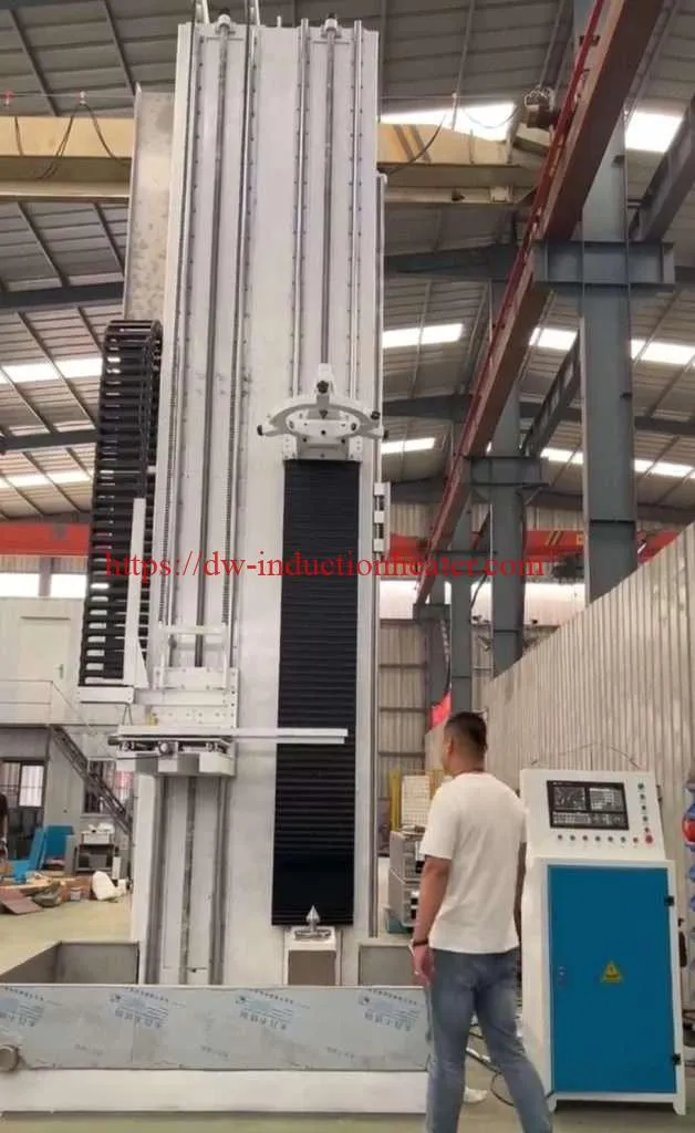
As industries continue to demand higher performance and longer service life from large-diameter components, advancements in induction hardening technologies are expected. Developments in process monitoring and control systems, coil design optimization, and the integration of simulation and modeling tools will further improve the efficiency and quality of the induction hardening process. Large CNC Induction Hardening-quenching machineX. FAQs Q1: What is the typical hardness range achieved through induction hardening of large-diameter components? A1: The hardness range achieved through induction hardening depends on the material and the desired application. For steels, hardness values typically range from 50 to 65 HRC (Rockwell Hardness Scale C), providing excellent wear resistance and fatigue strength. Q2: Can induction hardening be applied to non-ferrous materials? A2: While induction hardening is primarily used for ferrous materials (steels and cast irons), it can also be applied to certain non-ferrous materials, such as nickel-based alloys and titanium alloys. However, the heating mechanisms and process parameters may differ from those used for ferrous materials. Q3: How does the induction hardening process affect the core properties of the component? A3: Induction hardening selectively hardens the surface layer while leaving the core material relatively unaffected. The core retains its original ductility and toughness, providing a desirable combination of surface hardness and overall strength and impact resistance. Q4: What are the typical quenching media used for induction hardening of large-diameter components? A4: Common quenching media for large-diameter components include water, polymer solutions, and gas (air or nitrogen). The choice of quenching medium depends on factors such as the component's size, geometry, and the desired cooling rate and hardness profile. Q5: How is the depth of the hardened case controlled in induction hardening? A5: The depth of the hardened case is primarily controlled by adjusting the induction frequency and power levels. Higher frequencies result in shallower case depths due to the skin effect, while lower frequencies allow for deeper penetration. Additionally, the heating time and cooling rate can also influence the case depth.
https://dw-inductionheater.com/induction-hardening-of-large-diameter-shafts-and-cylinders.html?feed_id=238957&_unique_id=66057aaf24b72

关注者

博客归档

我的简介

我的照片
HLQ induction heating machine manufacturer provides the service of induction brazing,melting,hot forming,hardening surface,annealing,shrink fitting,PWHT,etc.