2023年2月28日星期二

Jointing Metal with Brazing and Welding

Jointing Metal with Brazing and Welding


There are several methods available for joining metals, including welding, brazing and soldering. What is the difference between welding and brazing? What is the difference between brazing and soldering? Let’s explore the distinctions plus comparative advantages as well as common applications. This discussion will deepen your understanding of metal joining and help you identify the optimal approach for your application.

HOW BRAZING WORKS


A brazed joint is made in a completely different manner from a welded joint. The first big difference is in temperature – brazing does not melt the base metals. This means that brazing temperatures are invariably lower than the melting points of the base metals. Brazing temperatures are also significantly lower than welding temperatures for the same base metals, using less energy.

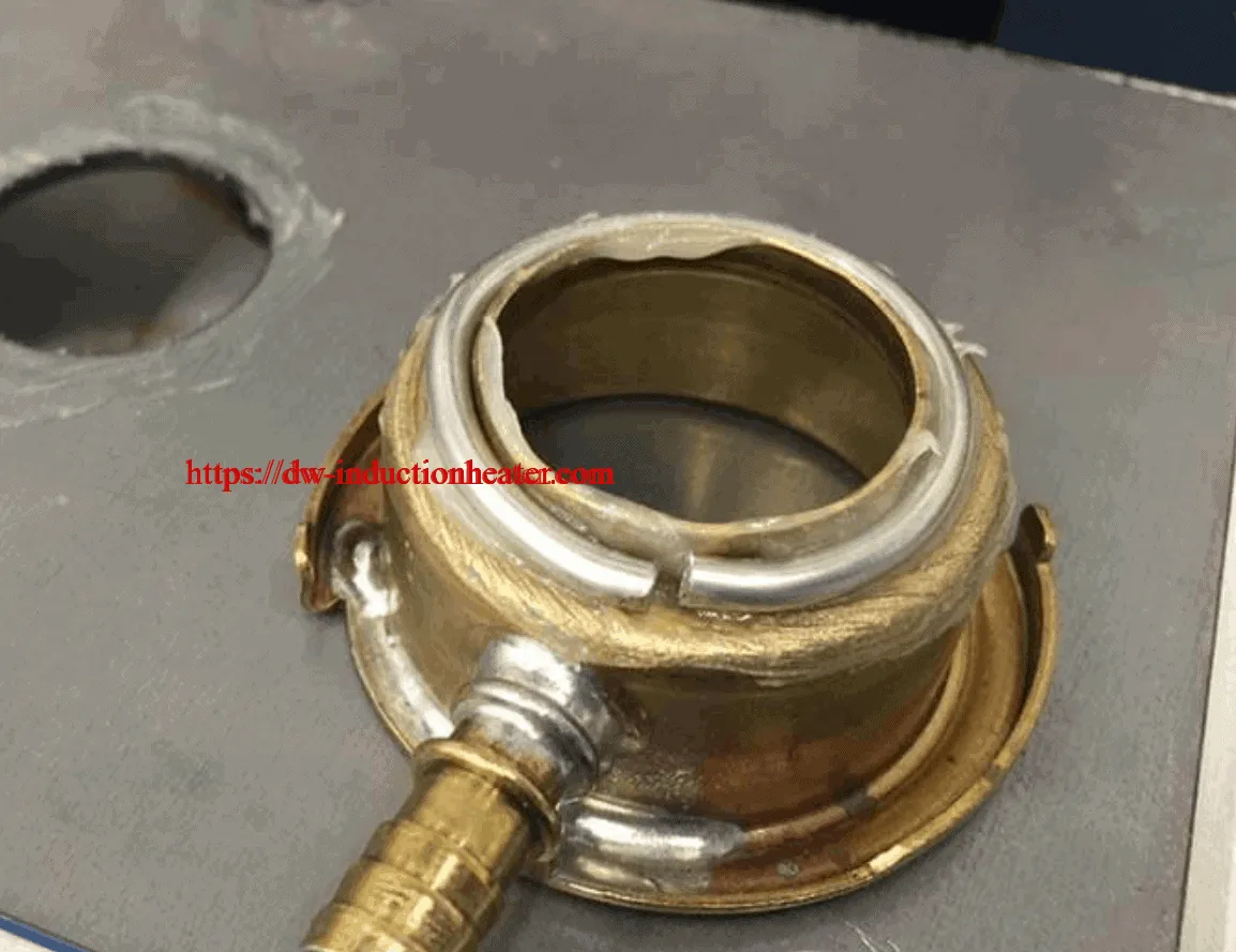
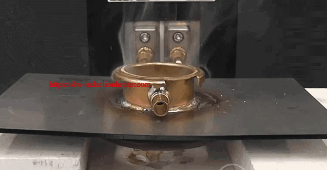
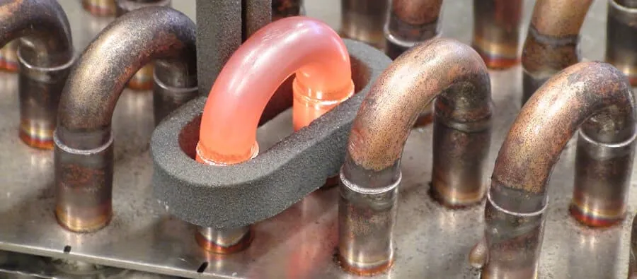
If brazing doesn’t fuse the base metals, how does it join them? It works by creating a metallurgical bond between the filler metal and the surfaces of the two metals being joined. The principle by which the filler metal is drawn through the joint to create this bond is capillary action. In a brazing operation, you apply heat broadly to the base metals. The filler metal is then brought into contact with the heated parts. It is melted instantly by the heat in the base metals and drawn by capillary action completely through the joint. This is how a brazed joint is made.

Brazing applications include electronics/electrical, aerospace, automotive, HVAC/R, construction and more. Examples range from air conditioning systems for automobiles to highly sensitive jet turbine blades to satellite components to fine jewelry. Brazing offers a significant advantage in applications that require joining of dissimilar base metals, including copper and steel as well as non-metals such as tungsten carbide, alumina, graphite and diamond.

Comparative Advantages. First, a brazed joint is a strong joint. A properly made brazed joint (like a welded joint) will in many cases be as strong or stronger than the metals being joined. Second, the joint is made at relatively low temperatures, ranging from about 1150°F to 1600°F (620°C to 870°C).

Most significant, the base metals are never melted. Since the base metals are not melted, they can typically retain most of their physical properties. This base metal integrity is characteristic of all brazed joints, including both thin- and thick-section joints. Also, the lower heat minimizes danger of metal distortion or warping. Consider too, that lower temperatures require less heat – a significant cost-saving factor.

Another important advantage of brazing is the ease of joining dissimilar metals using flux or flux-cored/coated alloys. If you don’t have to melt the base metals to join them, it doesn’t matter if they have widely different melting points. You can braze steel to copper as easily as steel to steel. Welding is a different story because you must melt the base metals to fuse them. This means that if you try to weld copper (melting point 1981°F/1083°C) to steel (melting point 2500°F/1370°C), you must employ rather sophisticated and expensive welding techniques. The total ease of joining dissimilar metals through conventional brazing procedures means you can select whatever metals are best suited to the function of the assembly, knowing you’ll have no problem joining them no matter how widely they vary in melting temperatures.

Also, a brazed joint has a smooth, favorable appearance. There is a night-and-day comparison between the tiny, neat fillet of a brazed joint and the thick, irregular bead of a welded joint. This characteristic is especially important for joints on consumer products, where appearance is critical. A brazed joint can almost always be used “as is,” without any finishing operations needed – another cost savings.

Brazing offers another significant advantage over welding in that operators can usually acquire brazing skills faster than welding skills. The reason lies in the inherent difference between the two processes. A linear welded joint must be traced with precise synchronization of heat application and deposition of filler metal. A brazed joint, on the other hand, tends to “make itself” through capillary action. In fact, a considerable portion of the skill involved in brazing is rooted in the design and engineering of the joint. The comparative speed of highly skilled operator training is an important cost factor.

Finally, metal brazing is relatively easy to automate. The characteristics of the brazing process – broad heat applications and ease of filler metal positioning – help eliminate the potential for problems. There are many ways to heat the joint automatically, many forms of brazing filler metal and many ways to deposit them so that a brazing operation can easily be automated for almost any level of production.

HOW WELDING WORKS


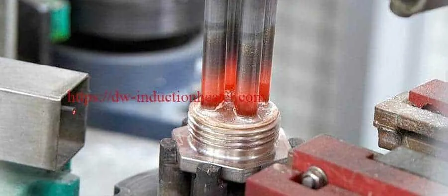
Welding joins metals by melting and fusing them together, typically with the addition of a welding filler metal. The joints produced are strong – usually as strong as the metals joined, or even stronger. To fuse the metals, you apply a concentrated heat directly to the joint area. This heat must be of a high temperature to melt the base metals (the metals being joined) and the filler metals. Therefore, welding temperatures start at the melting point of the base metals.

Welding is generally suited to joining large assemblies where both metal sections are relatively thick (0.5”/12.7mm) and joined at a single point. Since the bead of a welded joint is irregular, it is not typically used in products requiring cosmetic joints. Applications include transportation, construction, manufacturing and repair shops. Examples are robotic assemblies plus fabrication of pressure vessels, bridges, building structures, aircraft, railway coaches and tracks, pipelines and more.

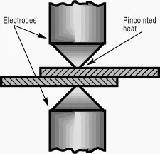
Comparative Advantages. Because welding heat is intense, it is typically localized and pinpointed; it is not practical to apply it uniformly over a broad area. This pinpointed aspect has its advantages. For example, if you want to join two small strips of metal at a single point, an electrical resistance welding approach is practical. This is a fast, economical way to make strong, permanent joints by the hundreds and thousands.

If the joint is linear rather than pinpointed, though, problems arise. The localized heat of welding can become a disadvantage. For example, if you want to butt-weld two pieces of metal, you begin by beveling the edges of the metal pieces to allow room for the welding filler metal. Then you weld, first heating one end of the joint area to melting temperature, then slowly moving the heat along the joint line, depositing filler metal in synchronization with the heat. This is a typical, conventional welding operation. Properly made, this welded joint is at least as strong as the metals joined.

However, there are disadvantages to this linear-joint-welding approach. The joints are made at high temperatures – high enough to melt both base metals and filler metal. These high temperatures can cause problems, including possible distortion and warping of the base metals or stresses around the weld area. These dangers are minimal when the metals being joined are thick, but they may become problems when the base metals are thin sections. Also, high temperatures are expensive, since heat is energy and energy costs money. The more heat you need to make the joint, the more the joint will cost to produce.

Now, consider the automated welding process. What happens when you join not one assembly, but hundreds or thousands of assemblies? Welding, by its nature, presents problems in automation. A resistance-weld joint made at a single point is relatively easy to automate. However, once the point becomes a line – a linear joint – once again, the line must be traced. It's possible to automate this tracing operation, moving the joint line, for example, past a heating station and feeding filler wire automatically from big spools. This is a complex and exacting setup, though, warranted only when you have large production runs of identical parts.

Keep in mind that welding techniques do continually improve. You can weld on a production basis via electron beam, capacitor discharge, friction and other methods. These sophisticated processes usually call for specialized and expensive equipment plus complex, time consuming setups. Consider if they are practical for shorter production runs, changes in assembly configuration or typical day-to-day metal joining requirements.

Choosing the Right Metal Joining Process
If you need joints that are both permanent and strong, you will likely narrow down your metal joining consideration to welding versus brazing. Welding and brazing both use heat and filler metals. They can both be performed on a production basis. However, the resemblance ends there. They work differently, so remember these brazing vs welding considerations:

Size of the assembly
Thickness of the base metal sections
Spot or line joint requirements
Metals being joined
Final assembly quantity needed
Other options? Mechanically fastened joints (threaded, staked or riveted) generally don’t compare to brazed joints in strength, resistance to shock and vibration, or leak-tightness. Adhesive bonding and soldering will provide permanent bonds, but generally, neither can offer the strength of a brazed joint –equal to or greater than that of the base metals themselves. Nor can they, as a rule, produce joints that offer resistance to temperatures above 200°F (93°C). When you need permanent, robust metal-to-metal joints, brazing is a strong contender.

Magnetic Induction Heater Manufacturer

Magnetic Induction Heater  is a process equipment which is used to melt,braze,forge,bond,heat treating,harden or soften metals or other conductive materials. For many modern manufacturing processes, Magnetic induction heating equipment offers an attractive combination of speed, consistency and control.The basic principles of magnetic induction heating have been understood and applied to manufacturing since the 1920s. During World War II, the technology developed rapidly to meet urgent wartime requirements for a fast, reliable process to harden metal engine parts. More recently, the focus on lean manufacturing techniques and emphasis on improved quality control have led to a rediscovery of induction technology, along with the development of precisely controlled, all solid state induction power supplies.

Magnetic Induction Heater relies on the unique characteristics of induction heating radio frequency (RF) energy - that portion of the electromagnetic spectrum below infrared and microwave energy. Since heat is transferred to the product via electromagnetic waves, the part never comes into direct contact with any flame, the inductor itself does not get hot, and there is no product contamination. When properly set up, the process becomes very repeatable and controllable.

Main Characteristics:
   1.IGBT module and soft switiching inverting technologies are as in the production of the generator,higher reliability can be do. 
   2. Small and portable ,compared with SCR controlled machine only 1/10 working space is needed. 3.  High efficiency to save energy,high efficiency and power far can be maintained
   4.  The generator is adatable in a large frequency range from 1KHZ to 1100KHZ,installation can be done very easily according to our manual.  
     5. 100%duty cycle ,continuous working ability at maximum power.  
     6. Constant power or constant voltage control mode.
     7. Display of output power,output frequency,and output voltage.
Series
Model
Input power Max
Input current Max
Oscillate frequency
Input Voltage
Duty cycle
M
.
F
.
DW-MF-15 Induction Generator
15KW
23A
1K-20KHZ According to the application
3*380V
380V±20%
100%
DW-MF-25 Induction Generator
25KW
36A
DW-MF-35Induction Generator
35KW
51A
DW-MF-45 Induction Generator
45KW
68A
DW-MF-70 Induction Generator
70KW
105A
DW-MF-90 Induction Generator
90KW
135A
DW-MF-110 Induction Generator
110KW
170A
DW-MF-160 Induction Generator
160KW
240A
DW-MF-45 Induction Heating Rod Forging Furnace
45KW
68A
1K-20KHZ
3*380V
380V±20%
100%
DW-MF-70 Induction Heating Rod Forging Furnace
70KW
105A
DW-MF-90 Induction Heating Rod Forging Furnace
90KW
135A
DW-MF-110 Induction Heating Rod Forging Furnace
110KW
170A
DW-MF-160 Induction Heating Rod Forging Furnace
160KW
240A
DW-MF-15   Induction Melting Furnace
15KW
23A
1K-20KHZ
3*380V
380V±20%
100%
DW-MF-25   Induction Melting Furnace
25KW
36A
DW-MF-35   Induction Melting Furnace
35KW
51A
DW-MF-45   Induction Melting Furnace
45KW
68A
DW-MF-70   Induction Melting Furnace
70KW
105A
DW-MF-90   Induction Melting Furnace
90KW
135A
DW-MF-110 Induction Melting Furnace
110KW
170A
DW-MF-160 Induction Melting Furnace
160KW
240A
DW-MF-110 Induction Hardening Equipment
110KW
170A
1K-8KHZ
3*380V
380V±20%
100%
DW-MF-160Induction Hardening Equipment
160KW
240A
H
.
F
.
DW-HF-04 Series
DW-HF-4KW-A
4KVA
15A
100-250KHZ
Single phase 220V
80%
DW-HF-15 Series
DW-HF-15KW-A
DW-HF-15KW-B
15KVA
32A
30-100KHZ
Single phase 220V
80%
DW-HF-25 Series
DW-HF-25KW-A
DW-HF-25KW-B
25KVA
23A
20-80KHZ
3*380V
380V±20%
100%
DW-HF-35 Series
DW-HF-35KW-B
35KVA
51A
DW-HF-45 Series
DW-HF-45KW-B
45KVA
68A
DW-HF-60 Series
DW-HF-60KW-B
60KVA
105A
DW-HF-80 Series
DW-HF-80KW-B
80KVA
130A
DW-HF-90 Series
DW-HF-90KW-B
90KVA
160A
DW-HF-120 Series
DW-HF-120KW-B
120KVA
200A
U
.
H
.
F
.
DW-UHF-3.2KW
3.2KW
13A
1.1-2.0MHZ
Single phase220V ±10%
100%
DW-UHF-4.5KW
4.5KW
20A
DW-UHF-045T
4.5KW
20A
DW-UHF-045L
4.5KW
20A
DW-UHF-6KW-I
6.0KW
28A
DW-UHF-6KW-II
6.0KW
28A
DW-UHF-6KW-III
6.0KW
28A
DW-UHF-10KW
10KW
15A
100-500KHZ
3*380V
380V±10%
100%
DW-UHF-20KW
20KW
30A
50-250KHZ
DW-UHF-30KW
30KW
45A
50-200KHZ
DW-UHF-40KW
40KW
60A
50-200KHZ
DW-UHF-6, 0KW
60KW
90A
50-150KHZ
Induction_heating_catalogue.pdf

Induction annealing copper wires

Continuous Induction annealing copper wires with High frequency heating system

Objective Continuously anneal a copper wire used in electric motors at a rate of 16.4 yds (15m) per minute to eliminate work hardening caused during the drawing process.
Material Square copper wire 0.06” (1.7mm) dia., temperature indicating paint
Temperature 842 ºF (450 ºC)
Frequency 300 kHz
Equipment • DW-UHF-60kW induction heating system, equipped with a remote workhead containing eight 1.0μF capacitors for a total of 8.0μF
• An induction heating coil designed and developed specifically for this application.
Process A twelve turn helical coil is used. A ceramic tube is placed inside the coil to isolate the copper wire from the copper coil and to allow the copper wire to flow smoothly through the coil.
Power runs continuously to anneal at a rate of 16.4 yds (15m) per minute.
Results/Benefits Induction heating provides:
• Hands-free heating that involves no operator skill for manufacturing
• Flameless process
• Ideal for in-line production processes

induction brazing stainless steel to copper

Objective Induction Brazing stainless steel to copper tubing. Objective is to evaluate induction brazing solution. Customer is looking to reduce defects and for a cleaner brazing environment. Due to different pipe size and lower volume – evaluation is performed with a induction brazing system.
Test1 Equipment DW-HF-25kw induction brazing machine Materials Copper to Stainless steel tube Power: 12.5kW Temperature: 1400ºF to 1600ºF (760ºC to 871ºC) Time: 9 to 11 seconds
Test2 Equipment DW-HF-25kw induction brazing machine Materials Copper to Stainless steel Power: 12.5kW Temperature: 1400ºF to 1600ºF (760ºC to 871ºC) Time: 9 to 11 seconds
Results and Conclusions: Induction brazing test with U open coil was able to braze the parts in 9 to 11 seconds for the full braze cycle. Operator training with this setup will be minimal.

brazing short circuit rings with induction heater

Induction Brazing of short circuit rings of electrical motors


Short-circuit ring is brazed to rotors in electric motors, particularly in the motors called “squirrel cage”, name used to call the rotor and the whole motor itself. The temperature homogeneity in the ring is absolutely critical to meet the technical requirements in the final motor or generator. So the control process and brazing experience in this field are a must.

Induction heating offers numerous advantages over traditional flame methods for brazing short-circuit rings (SCRs). One key advantage is that induction generates a more homogeneous temperature distribution around the SCR. Also, as induction heating can be very precisely controlled, overheating of the copper bars is avoided. Finally, induction heating is fast. Its accuracy and repeatability means it can boost throughput without sacrificing quality.

SCR/ short circuit ring induction brazing can be done in two ways: single shot and segment brazing. The major difference between the two methods is that the former needs more heating power. When the diameter of the SCR is less than 1200 mm, single shot brazing is used.HLQ Induction Equipment’s series power generators provide a wide range of heating power from 25 KW up to 200/320 KW. A temperature regulating system can be integrated into infrared temperature controller for closed loop control of the brazing power.  Normally there are two controlled pyrometers in the system: one for measuring the temperature in the SCR and the other for measuring the temperature on the copper bar to ensure it reaches the brazing temperature.


HLQ Induction’s unique induction heating coil design, together with induction heating’s speed and accuracy, mean minimal heat inputs. This in turn reduces the risk of shafts weakening, and minimizes heat transfer into the laminations, a common problem when using flame brazing. Induction brazing also prevents other problems associated with flame heating. For example, the accuracy of induction heating reduces the risk of ovality, and the subsequent need to re-balance squirrel cage motors. Open flames risk overheating the flux material,

compromising its capability to prevent the formation of oxides in the joint. The copper, too, risks overheating, which can lead to unwanted grain growth. But with induction heating the temperature is precisely controlled. Induction heating also has environmental and safety advantages. It’s easy to remove any fumes. Noise levels and ambient temperature increases are negligible.

HLQ Induction can provide customized, turn-key solutions for virtually any SCR brazing task. These solutions include the equipment, optimized temperature curves, customized coils and a comprehensive range of training and service support.

HLQ Induction Equipment Co provides solutions covering either Medium to High Power motors and generators with more than 20 year experience around the world. This application in part of a wider portfolio for this industry.

INDUCTION BRAZING BENEFITS vs ALTERNATIVE PROCESSES

Controlled process: homogenization of the heating and temperature control all around the ring  .

Fast process (higher power density), about 10 times less than flame

Heating by ramps totally controlled and warranted or even cooling by ramps

Repeatability and traceability


SIMPLIFIED PROCESS

1.No dedusting required

2.Less distortions, no rebalanced required

3.Low oxide formation

4.Operator expertise brazing skills are not too critical

5.Running costs lower than torch

6.ECO & USER-FRIENDLY OPERATION

Safer process:

1.No flame or gas, minimized risks

2.Clear view of the process by operator at any moment

3.Environmental friendly

4.Easy to remove fumes

Induction Brazing Solution:

HLQ Induction Brazing Solutions for short-circuit ring brazing cover either Medium to High Power motors and generators.

1.Specialized coil for extreme temperature uniformity all over the ring

2.Advanced temperature control either fully atomized process or managed by the brazer


RELATED PRODUCTS

Rotor Short circuit ring brazing​

Stator Copper Strip brazing​

Rotor Shaft shrink fitting​

Housing shrink fitting

2023年2月27日星期一

Annealing Metal Stamp With Induction

Annealing Metal Stamp With Induction Objective: Induction Heating the opposite end of a metal stamp so that it mushrooms instead of cracks/splits when struck by a hammer. Material S-7 steel of varying rectangular cross sectional sizes Temperature 1400-1800 ºF (760-982) ºC Frequency 300 kHz Equipment DW-UHF-10KW, induction heating system, equipped with a remote heat station containing two 1.5 μF capacitors for a total of 0.75 μF and three different induction heating coils designed and developed specifically for this application. Process One five-turn and two four-turn helical coils are used to heat the end of stamps to the required temperature. Two part sizes can be run in each of coils, using the same machine settings except for cycle time. Cycle rates dependent upon the crosssection size. The 3/8" (0.9525 cm) square size is has a rate of below 10 seconds. The rate for the middle size, ½" – 1 ½ " (1.27 - 3.81 cm) is 30 to 60 seconds. A 1" (2.54 cm) square part takes approximately two minutes. Fixturing can influence the length of the cycle time required. For shorter heat times a larger power supply may be used. Results/Benefits Precise heat only to the area that needs annealing is more efficient and repeatable than heating with a torch.  

Advantages of Induction Heating

what is advantages of induction heating,brazing,hardening,melting and forging,etc?


Why choose induction heating over open flame,convection,radiant or another heating method?Here's a short summary of the major advantages that modern solid state induction heating offers for lean manufacturing:

*Heating Fast

Induction heating is induced within the part itself by alternating electrical current. As a result, product warpage, distortion and reject rates are minimized. For maximum product quality, the part can be isolated in an enclosed chamber with a vacuum, inert or reducing atmosphere to eliminate the effects of oxidation. Production rates can be maximized because induction works so quickly; heat is developed directly and instantly (>2000º F. in < 1 second) inside the part. Startup is virtually instantaneous; no warm up or cool down cycle is required. The induction heating process can be completed on the manufacturing floor, next to the cold or hot forming machine, instead of sending batches of parts to a remote furnace area or subcontractor. For example, a brazing or soldering process which previously required a time-consuming, off-line batch heating approach can now be replaced with a continuous, one-piece flow manufacturing system.

*Heating Consistent

Induction heating eliminates the inconsistencies and quality issues associated
with open flame, torch heating and other methods. Once the system is properly calibrated and set up, there is no guess work or variation; the heating pattern is repeatable and consistent. With modern solid state systems, precise temperature control provides uniform results; power can be instantly turned on or shut off. With closed loop temperature control, advanced induction heating systems have the capability to measure the temperature of each individual part. Specific ramp up, hold and ramp down rates can be established & data can be recorded for each part that is run.


*Heating Clean

Induction heating systems do not burn traditional fossil fuels; induction is a clean, non-polluting process which will help protect the environment. An induction system improves working conditions for your employees by eliminating smoke, waste heat, noxious emissions and loud noise. Heating is safe and efficient with no open flame to endanger the operator or obscure the process. Non-conductive materials are not affected and can be located in close proximity to the heating zone without damage.

*Save Energy

Tired of increasing utility bills? This uniquely energy-efficient process converts up to 90% of the energy expended energy into useful heat; batch furnaces are generally only 45% energy-efficient. And since induction requires no warm-up or cool-down cycle, stand-by heat losses are reduced to a bare minimum. The repeatability and consistency of the induction process make it highly compatible with energy-efficient automated systems.

Induction Billets Heater Video

Induction Billets Heater Video

[embed]https://youtu.be/TuTzgyUYXe8[/embed]

Brazing Aluminum Tubes with Induction Heating

Induction Brazing Aluminum Tubes with High Frequency Induction Heating


The novel applications areas of induction heating require analyzing the temperature distribution inside the heated components taking into account the corresponding structures and the material properties. The finite element method (FEM) provides a powerful tool to perform such analyses and optimization of induction heating processes through coupled electromagnetic and thermal numerical analyses and simulations.


The main aim of this contribution is to indicate the possibility of application of the proper, sophisticated and efficient induction brazing technology for the manufacturing of solar collectors based on numerical simulation and performed experiments.

Problem description


This work deals with the design of components for solar collectors suitable for brazing process, namely the parts of collecting tubing (Fig. 1a). Tubes are made from the Al alloy of the AW 3000 type with the chemical composition given in the Table 1. For brazing, the alloy of Al 104 type is used (Table 2) together with the flux Braze Tec 32/80 which residues are non-corrosive. The temperature interval between solidus and liquidus temperatures for the Al 104 brazing alloy ranges from 575 °C to 585 °C. The solidus temperature of the tube material is 650 °C.

Table 1 Chemical composition of AW 3000 alloy [wt. %]


Si Fe Cu Mn Mg Zn Cr Al
0.05-0.15 0.06-0.35 max. 0.1 0.3-0.6 0.02-0.20 0.05-0.3 max. 0.25 balance

Table 2 Chemical composition of the brazing alloy of the Al 104 type [wt. %]


Si Fe Cu Mn Mg Zn Ti Al
11-13 0.6 max. 0.3 0.15 0.1 0.2 max. 0.15 balance

The brazing process supposes the application of induction heating. It is necessary to design the system of induction heating in such a manner that brazing temperatures should be achieved in the joint zone (brazed metals – brazing alloy) in the same time. From this viewpoint, a proper selection of induction coil, its geometry and operation parameters (mainly the frequency and the source current) is very important. The shape and dimensions of the designed copper water-cooled induction coil are shown in Fig. 1b


The effect of relevant parameters of induction heating on the temperature distribution in the brazed parts was assessed using the numerical simulation of induction heating applying the program code ANSYS 10.0.

Simulation model


In accordance with the methodology of solution of coupled electromagnetic and thermal problems by FEM using the ANSYS 10.0 software [3-5], the simulation model of induction heating process for brazing was developed including geometrical, physical, and initial and boundary conditions. The main aim of numerical simulation was to define the optimum parameters of induction heating (the frequency and the source current) to achieve the required temperature distribution in the zone of joint formation.

Suggested 3D-model (Fig. 2) for electromagnetic analysis consists of the model of tubes, brazing alloy, water-cooled induction coil and surrounding air (not shown in Fig. 2). In the thermal analysis, only the tubes and brazing alloy were considered. A detail of the mesh generated from the linear, 8-node elements in the zone of joint formation is illustrated in Fig. 2b.


Fig. 2 a) Geometrical model for electromagnetic analysis without surrounding air and b) detail of the 3D mesh generated in the zone of joint formation.The temperature dependences of electric and thermal properties of AW 3000 alloy and Al 104 brazing alloy were obtained using JMatPro software [6]. Following from the fact that the applied materials are non-magnetic, their relative permeability µr = 1.

The initial temperature of brazed materials was 20 °C. Perfect electric and thermal contacts on the boundary surfaces of materials were supposed. The frequency of the source current in the induction coil was supposed to be 350 kHz. The value of the source current was defined from the interval from 600 A to 700 A. Cooling of the brazed tubes by free convection and radiation to the air with the temperature of 20 °C was taken into account. Combined heat transfer coefficient dependent on the surface temperature of brazed parts was defined. In Fig. 3, the temperature distribution in brazed components after the achievement of required temperatures in the joint zone are shown for chosen values of applied source currents in induction heating coil. The time of 36 seconds using the source current of 600 A seems to be quite long. The fast heating applying the source current of 700 A cannot be sufficient for the melting of the Al 104 brazing alloy. In this reason the source current approximately of the level of 620 A to 640 A is recommended leading to the brazing times from 25 to 27.5 seconds......


Brazing Aluminum Tubes with Induction Heating

Induction Brazing Stainless Steel

Induction Brazing Stainless Steel Objective 1st Application: Braze hub assembly to needle holder 2nd Application: Braze Large tube to ring joint Material: 1st Application: Steel hub assembly and needle 0.1" dia(2.5mm) 2nd Application: Steel tube 1" OD (25.4 mm) and ring Temperature 1400 ºF (760 ºC) Frequency 325 kHz for brazing the needle 0.1" dia (2.5mm) 259 kHz for brazing ring to steel tube 1" OD (25.4 mm) Equipment • DW-UHF-4.5KW induction heating system, equipped with a remote workhead containing two .66 μF capacitors for a total of 1.32 μF • Two induction heating coils, designed and developed specifically for this dual application. Process 1st application: A two-turn helical coil is used to heat the hub assembly on the needle holder for 10 seconds. The coil concentrates the heat on the hub only, as the needle is magnetic and the hub material is non-magnetic. A small diameter braze wire is used to supply sufficient amount of braze creating a strong aesthetically pleasing bond. 2nd application: A three-turn helical coil is used for brazing the large tube to the ring joint for 3-5 minutes. A braze ring is used to supply sufficient amount of braze to create an aesthetically pleasing bond. Results/Benefits Induction heating provides: • Even distribution of heating, provides even flow of braze alloy for an aesthetically pleasing bond • System flexibility allows for the same unit to be used for two different applications which is a cost saving.

induction soldering copper tubing to brass valves


High frequency induction soldering copper tubing to brass valves


Objective:

Test: Induction Soldering copper tubing to brass valves

Industry: HVAC

Materials: Copper and brass pipes


Equipment: DW-HF-25kw induction heating machine

Power: 16 kW

Temperature932oF (500oC)

Time: 20 seconds

Coil: Coated custom-made coil.


The Process:


This application request was brought to HLQ Induction Heating Power’s attention by a HVAC company. Their goal was to eliminate their current use of the torch method, as well as remove defects and improve the safety for operators. To start the test, our applications engineer assembled the setup of copper tubing and brass valves. After applying flux to each joint the engineer heated them for 20 seconds. Solder was manually applied after the joints reached 932oF (500C), and created an even solder around the joints.  The use of induction heating was successful in this HVAC application.


2023年2月26日星期日

Induction Preheating Welding Steel Pipe

Induction Preheating Welding Steel Pipe With High Frequency Heating System Objective To preheat a steel pipe to 500ºF (260ºC) before welding. Material Steel shaft assembly 5” to 8” OD (127-203.2mm) with a 2” (50.8mm) heat zone. Temperature 500ºF (260ºC), if higher temperatures are required, heat time can be increased. Frequency 60 kHz Equipment • DW-HF-60kW induction heating system, equipped with a remote workhead containing eight 1.0 μF capacitors for a total of 8 μF. • An induction heating coil designed and developed specifically for this application. Process A multi-turn two position channel “C” coil, adjustable on a busbar is used to heat the desired heat zone. The coil is adjustable to fit various diameter pipes. The shaft is rotated in a fixture and heated for 3 minutes to achieve a temperature of 500ºF (260ºC). Results/Benefits Induction heating provides: • Preheating prevents shock to shaft which eliminates cracking in the welding phase. • Hands-free heating that involves no operator skill for manufacturing. • Even distribution of heating between the shank and the  sleeve. induction preheating welding steel pipe             induction preheating steel pipe before welding

induction Brazing copper rods to brass strips


Objective

Induction Brazing copper rods to brass strips to replace torch operation. The current torch process results in excessive contaminants on the assembly, and requires extensive rework after the induction brazing operation.


Equipment
DW-UHF-10KW INDUCTION BRAZING MACHINE

Two turn open end conveyor coil

Materials
• Copper coupon plate and copper rod
• Braze wire – EZ Flo 45
• Braze alloy – 45% Silver, 1/32 DIA


Key Parameters – TEST 1
Power: 7.2 kW
Temperature: Approximately 1350° F (732° C)
Time: Average time – 100 seconds

Process and Results:
For Induction brazing copper plate to copper rod,, EZ Flo 45 braze wire was cut into 2” lengths and placed in the interface area. In a production situation, EZ Flo 45 brazing paste is recommended. The assemblies were set up and heated for an average time of 100 seconds to flow the alloy and achieve the braze.


Key Parameters – TEST 1
Power: 6 kW
Temperature: Approximately 1350° F (732° C)
Time: Average time – 2.5 minutes

Process and Results:
For Induction brazing copper rod to brass plate,, EZ Flo 45 braze wire was cut into 2” lengths and placed in the interface area. In a production situation, EZ Flo 45 brazing paste is recommended. The assemblies were set up (see photographs) and heated for an average time of 2.5 minutes to flow the alloy and achieve the braze.

Due to the metal resistance differential between copper and brass, the brass bar heat preferentially. The induction heating coil designed to braze the bars to the plate section heats the rods and the heat is transferred to the plate more by conduction than induction causing the bars to initially reach temperature prior to the plate. If the materials are the same (cooper to copper or brass to brass, this is not a problem. If the bar is copper and the plate is brass there are not issues – only when the bar is brass and the plate is copper. This requires the power to be reduced to allow tie for heat transfer from the brass rod to the copper plate.


Key Parameters – TEST 1
Power: 7.2 kW
Temperature: Approximately 1350° F (732° C)
Time: Average time – 2 minutes

Process and Results:
For Induction braze copper coupon plate and copper rod,, EZ Flo 45 braze wire was cut into 2” lengths and placed in the interface area. In a production situation, EZ Flo 45 brazing paste is recommended.

The assemblies were set up  and heated for an average time of 2 minutes to flow the alloy and achieve the braze.


Results/Benefits:


  • induction brazing Strong durable joints

  • Selective and precise heat zone, resulting in less part distortion and joint stress than welding

  • Less oxidation

  • Faster heating cycles

  • More consistent results and suitability for large volume production, without the need for batch processing

  • Safer than flame brazing


Induction Soldering Brass to Steel Plate

High Frequency Induction Soldering Brass to Steel Plate Technology

Objective High Frequency Induction Soldering brass to steel plate Equipment DW-UHF-6KW-I handheld induction brazing heater
Materials Steel plate to brass part induction soldering using Harris Stay-Brite #8 Silver Bearing Solder and Harris Bridgit Lead Free Soldering Flux. Key Parameters Power: 2kW Temperature: 535°F to 585°F (279°C to 307°C) Time: 21 Seconds  

Induction Brazing Copper Assembly

Induction Brazing Copper Assembly With High Frequency Heating Equipment

Objective Brazing a copper pivot assembly
Material Two copper uprights 2” (5cm) wide x 4” (10.2cm) high, copper base 3” (7.6cm) x 2” (5cm) and .5” (1.3mm) thick with 2 channels for the uprights to the slide into, braze shims and black flux
Temperature 1350 ºF (732 ºC)
Frequency 200 kHz
Equipment •DW-UHF-20kW induction heating system, equipped with a remote workhead containing two 1.0μF capacitors for a total of 0.5μF
• An induction heating coil designed and developed specifically for this application.
Process A three turn helical coil is used to heat the base of the assembly. The copper uprights and two braze shims are placed in the grooves in the base and black flux is applied. The assembly is placed in the coil and power is applied for 4 minutes to braze both the uprights in place.
Results/Benefits Induction heating provides:
• Rapid localized heat which can minimize oxidation and reduce cleaning after joining
• Consistent and repeatable joints
• Hands-free heating that involves no operator skill for manufacturing
• Even distribution of heating

Induction Preheating Hot Rod Heading

Induction Preheating Hot Rod Heading With IGBT Heating Units

Objective Heat a waspaloy rod to 1500ºF (815.5ºC) for hot heading application
Material Waspaloy rod 0.5” (12.7mm)OD, 1.5” (38.1mm) length, ceramic liner
Temperature 1500 ºF (815.5ºC)
Frequency 75 kHz
Equipment • DW-HF- 20 kW induction heating system, equipped with a remote workhead containing two 1.32μF capacitors for a total of .66μF
• An induction heating coil designed and developed specifically for this application.
Process A seven turn helical coil is used to heat the rod. The rod is placed inside the coil and power is applied for two seconds
providing enough heat to penetrate the inner core. An optical pyrometer is used for close loop temperature control and a
ceramic liner is used so the rod does not touch the coil.
Results/Benefits Induction heating provides:
• Low pressure and minimal residual stress
• Better grain flow and microstructure
• Even distribution of heating
• Improved production rates with minimal defects

Preheating Hot Rod Heading

Automatic Induction Forging Video

Automatic Induction Forging Video of Induction Forging Furnace with Full-automatic Feeder System

2023年2月25日星期六

ultrasonic welding equipment | ultrasonic plastic welder for fabric

ultrasonic welding equipment | ultrasonic welder | ultra sonic plastic welder with Automatic Frequency Chasing


Ultrasonic welding is an industrial technique whereby high-frequency ultrasonic acoustic vibrations are locally applied to workpieces being held together under pressure to create a solid-state weld.


 ♦Fully automatic frequency chasing, suitable for various sizes of welding die and different design mold, automatic chasing frequency range:±400HZ

Example: 15KHZ ultrasonic, mold frequency in 14.4-15.2KHZ can Automatic frequency traceability

♦The use of CPU computer to monitor various programs is fast and adaptable. The built-in protection system "system protection monitoring" function will respond to the following situations: the temperature is too high and the pressure is too high, which leads to overload. Excessive current of ultrasonic generator, loosening of solder head, transducer or transducer, failure of generator circuit, etc.

♦Automatic tuning enables the ultrasonic generator to automatically track and compensate for changes in welding head frequency. When the temperature is too high, wear on the surface of the welding head or debris on the head, this frequency change will occur.

♦Built-in automatic constant amplitude system. The ultrasonic amplitude can be adjusted from 50% to 100% stepless to adapt to different welding work.

♦With IGBT, the reaction speed is 100 times faster than that of traditional silica gel power tube.

ultrasonic plastic welding machine-ultrasonic welder for plastic


Model 1520A 1526A 1532A 1542A
Frequency 15KHz
Power  2000W  2600W  3200W  4200W
 Voltage  220V
Capacity 10-20 times/min
Driving form Pneumatic
Stroke Length(Horn Journy) 75mm 100mm
Output Time 0.01-9.99S Adjustable
Welding Area Φ100 Φ200 Φ300 Φ400
Electricity AC
Control mode Numerical control
Working air pressure 1-7 Bar
Weight  90KG  90KG  90KG  120KG
Dimensions 450*750*1100mm 760*1000*1950mm

Ultrasonic Plastic Welder

Main Features
1. Ultrasonic Welding Plastic Machine, manually tuning, simple to use and maintenance.
2. Welding by time, delay time, weld time and hold time. Working pressure is adjustable.
4. Precise and high quality imported pneumatic parts
5. High quality transducer and booster.
6. Self-protection: Over-Current, Frequency Deviation, Over-Temperature
7. Available in 4 frequencies – 15 KHz, 20 KHz ,35 KHz and 40 KHz.
8. Quick application changeover, high welding seam strength.
9. Suitable for high cadences and short cycle times.

Ultrasonic Welding Horns/Ultrasonic Welding Molds:

ultrasonic welding horn-ultrasonic welding mold

Applications:

Ultrasonic welding plastic machine is widely used in automotive industry, electronic industry, medical industry, household appliances, woven apparel, office supplies, packaging industry, toy industry, and so on.

Automotive industry: plastic body parts, car doors, automotive dashboard, lights, mirrors, sun visor, interior parts, filters, reflective material, reflective spike, bumper, cable, plastic filter for motorcycle , Radiator, brake fluid tank, oil cups, water tanks, fuel tank, air hose, exhaust purifiers, the tray plate, and so on.

Plastic Electronics: prepaid water meters, communications equipment, cordless phones, mobile phone accessories, cell phone case, battery case, charger, maintenance valve regulated lead-acid batteries, 3-inch floppy disk, U disk, SD card, CF card, USB connection, Bluetooth devices, and so on.

Stationery: folder, album, folding boxes, PP hollow board, pen loops, ink cartridges, toner cartridges, and so on.

Medical and Daily products: watches, kitchen utensils, oral liquid bottle caps, drip caps, mobile phone accessories, golden soft brush, and daily necessities, handle, security caps, cosmetics bottle, coffee pot, washing machines, air dehumidifiers, Electric irons, electric kettles, vacuum cleaners, speakers, cover and metal face grille and other civil engineering and so on.

Health products: children's products, air mattresses, clothes hangers, gardening supplies, kitchenware sanitary ware, shower, shower head, and so on.

ultrasonic welding applications

ultrasonic welding process applications

ultrasonic welding machine-ultrasonic plastic welder


[wpforms id="3947"]

关注者

博客归档

我的简介

我的照片
HLQ induction heating machine manufacturer provides the service of induction brazing,melting,hot forming,hardening surface,annealing,shrink fitting,PWHT,etc.