2024年3月4日星期一

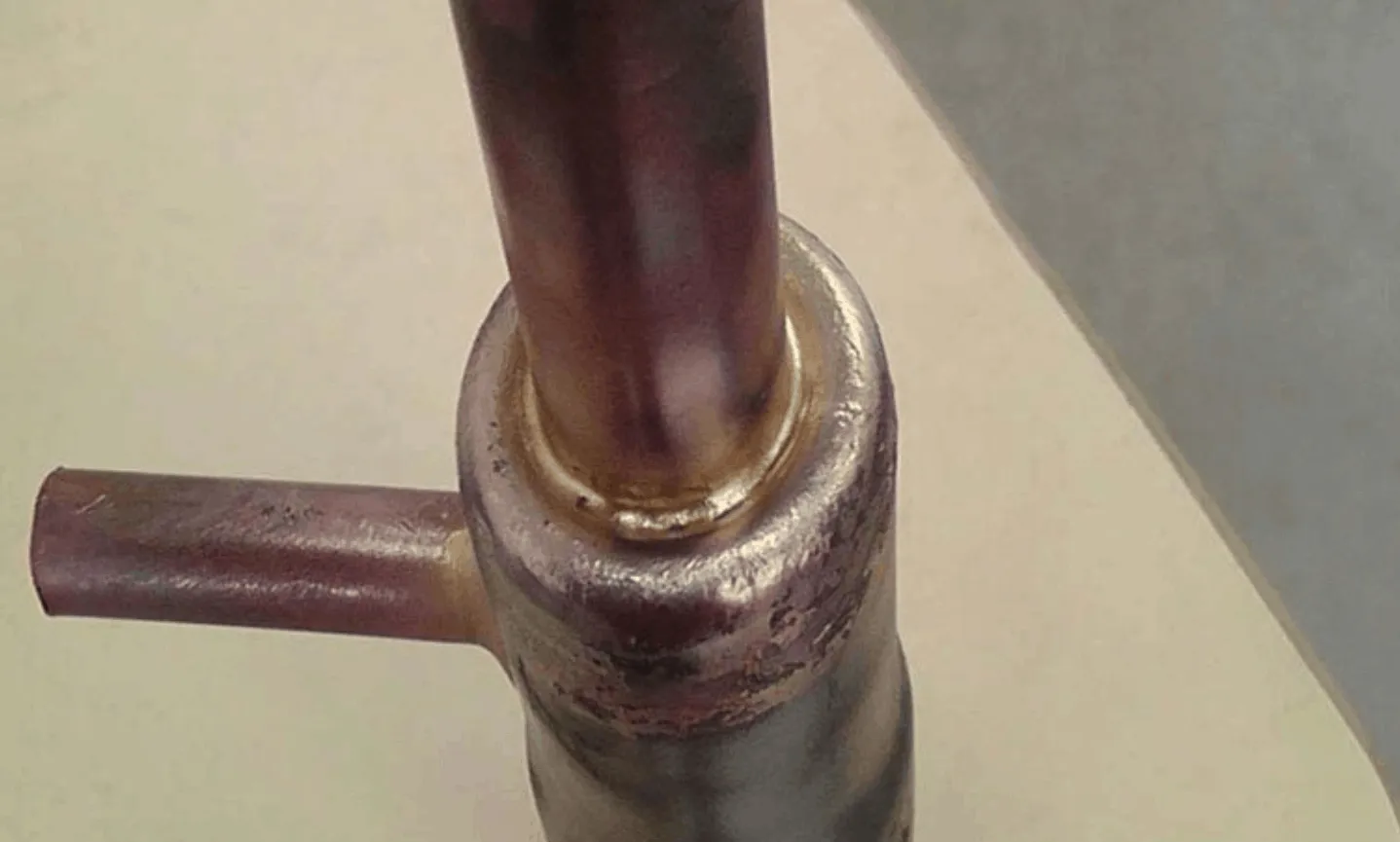
induction brazing steel tube to copper tube

High Frequency Induction Brazing Steel Tube to Copper Tube

Objective The goal is to braze a steel tube to a copper tube in 60 seconds using flux and brazing alloy.
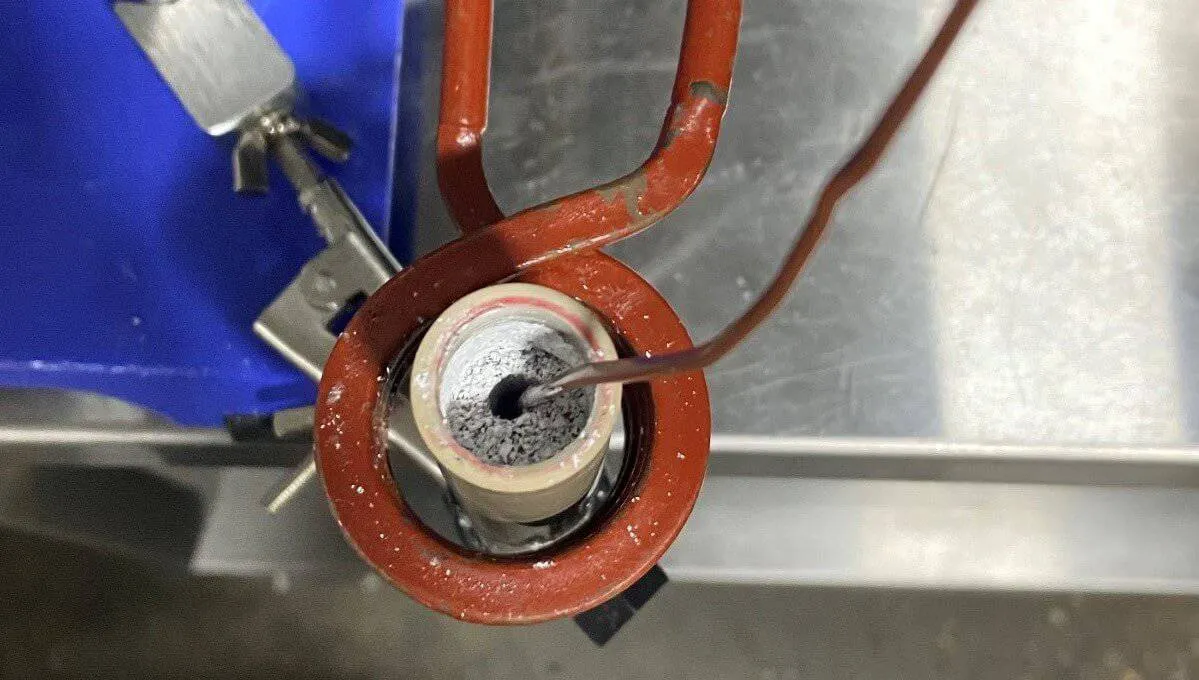
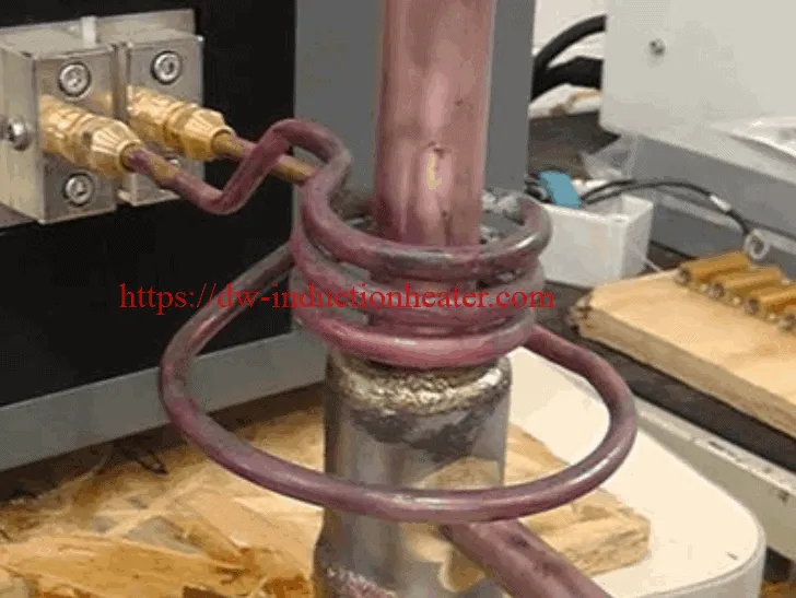
Equipment DW-UHF-10kw induction brazing heater Three turns dual diameter coil Materials • Steel tube and copper receiver • Braze alloy (CDA 681) • B-1 flux Key Parameters Temperature: Approximately 1750° F (954° C) Frequency: 148 kHz
Process:
  1. The assembly section was pre-assembled and fluxed (B-1) then located in the two diameter coil with a single pre-formed alloy ring set at the interface area.
  2. Alloy flow and joint completed in 60 seconds.
  3. The material was cooled in water following the completion of induction brazing.
  4. The joint was then cross-sectioned to validate that the brazing process had produced a strong, high quality joint.
Results/Benefits:
  • Strong durable joints with induction heating
  • Selective and precise heat zone, resulting in less part distortion and joint stress than welding
  • Less oxidation
  • Faster heating cycles
  • More consistent results and suitability for large volume production, without the need for batch processing
  • Safer than flame brazing
induction brazing steel tube to copper tube process
https://dw-inductionheater.com/induction-brazing-steel-tube-to-copper-tube.html?feed_id=235607&_unique_id=65e65518d8a86

High Frequency Welding

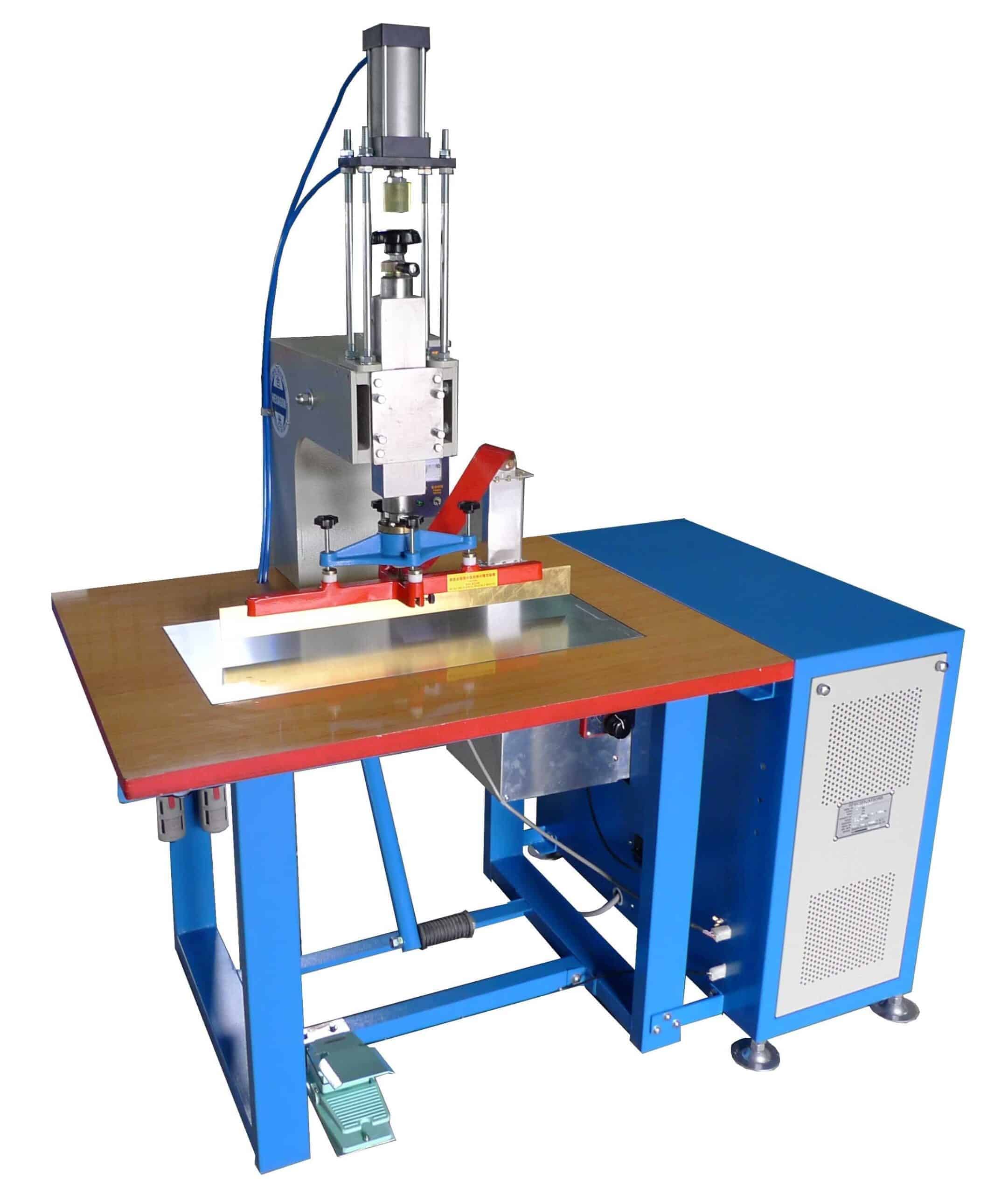
High Frequency Welding Machine Manufacturer/RF PVC welding machine for welding plastic,etc.

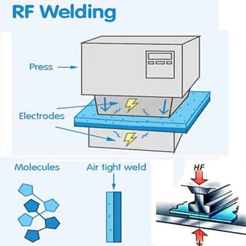
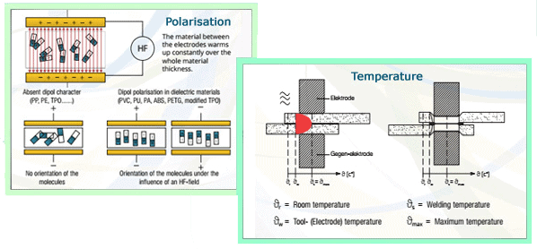
High Frequency Welding, known as Radio Frequency (RF) or Dielectric welding, is the process of fusing materials together by applying radio frequency energy to the area to be joined. The resulting weld can be as strong as the original materials. HF Welding relies on certain properties of the material being welded to cause the generation of heat in a rapidly alternating electric field. This means that only certain materials can be welded using this technique. The process involves subjecting the parts to be joined to a high frequency (most often 27.12MHz) electromagnetic field, which is normally applied between two metal bars. These bars also act as pressure applicators during heating and cooling. The dynamic electric field causes the molecules in polar thermoplastics to oscillate. Depending on their geometry and dipole moment, these molecules may translate some of this oscillatory motion into thermal energy and cause heating of the material. A measure of this interaction is the loss factor, which is temperature and frequency dependent.

Polyvinylchloride (PVC) and polyurethanes are the most common thermoplastics to be welded by the RF process. It is possible to RF weld other polymers including nylon, PET, PET-G, A-PET, EVA and some ABS resins, but special conditions are required, for example nylon and PET are weldable if preheated welding bars are used in addition to the RF power.

HF welding is generally not suitable for PTFE, polycarbonate, polystyrene, polyethylene or polypropylene. However, due to the impending restrictions in the use of PVC, a special grade of polyolefin has been developed which does have the capability to be HF welded.
The primary function of HF welding is to form a joint in two or more thicknesses of sheet material. A number of optional features exist. The welding tool can be engraved or profiled to give the entire welded area a decorative appearance or it can incorporate an embossing technique to place lettering, logos or decorative effects on the welded items. By incorporating a cutting edge adjacent to the welding surface, the process can simultaneously weld and cut a material. The cutting edge compresses the hot plastic sufficiently to allow the excess scrap material to be torn off, hence this process is often referred to as tear-seal welding.high frequency welding machine A typical plastic welder consists of a high frequency generator (which creates the radio frequency current), a pneumatic press, an electrode that transfers the radio frequency current to the material that is being welded and a welding bench that holds the material in place. The machine could also have a grounding bar that is often mounted behind the electrode, which leads the current back to the machine (grounding point). There are different types of plastic welders, the most common being tarpaulin machines, packaging machines and automated machines. By regulating the machine’s tuning, the field strength can be adjusted to the material being welded. When welding, the machine is surrounded by a radio frequency field that, if too strong, can heat up the body somewhat. This is what the operator needs to be protected from. The strength of the radio frequency field also depends on the type of machine being used. Generally, machines with visible open electrodes (unshielded) have stronger fields than machines with enclosed electrodes.
When describing radio frequency electromagnetic fields, the field’s frequency is often mentioned. The permitted frequencies for plastic welders are 13.56, 27.12, or 40.68 megahertz (MHz). The most popular industrial frequency for HF welding is 27.12MHz. The radio frequency fields from a plastic welder spread out around the machine, but most often it is only right next to the machine that the field is so strong that precautions need to be taken. The field’s strength decreases sharply with distance from the source. The strength of the field is given in two different measurements: the electric field strength is measured in volts per metre (V/m), and the magnetic field strength is measured in amperes per metre (A/m). Both of these must be measured to get an idea of how strong the radio frequency field is. The current that goes through you if you touch the equipment (contact current) and the current that that goes through the body when welding (induced current) must also be measured.

Advantages of High Frequency Welding Technology

  • HF sealing occurs from the inside out by using the material itself as a heat source. The heat is focused at the weld target so that the surrounding material does not have to be super-heated to arrive at a target temperature at the joint.
  • With HF heating is generated only when the field is energized. Once the generator cycles, the heat is turned off. This allows for greater control over the amount of energy that the material sees over the entire cycle. In addition, HF-generated heat does not radiate off the die like on a heated die. This prevents heat-degredation of the material abutting the weld.
  • HF tooling is usually run "cold". This means that once the HF is turned off, the material stops being heated, but remains under pressure. In this fashion it is possible to both instantly heat, weld, and cool the material under compression. More control over the weld results in more control over the resulting extrusion, thus increasing the weld strength.
  • RF welds are "clean" because the only material needed to produce an HF weld is the material itself. There are no adhesives or by-products involved in HF
high frequency welding principle
https://dw-inductionheater.com/high-frequency-welding.html?feed_id=235572&_unique_id=65e59e5f3fc39

2024年3月3日星期日

induction heating reactor tank-vessels

Induction Heating Reactors Tank-Vessels

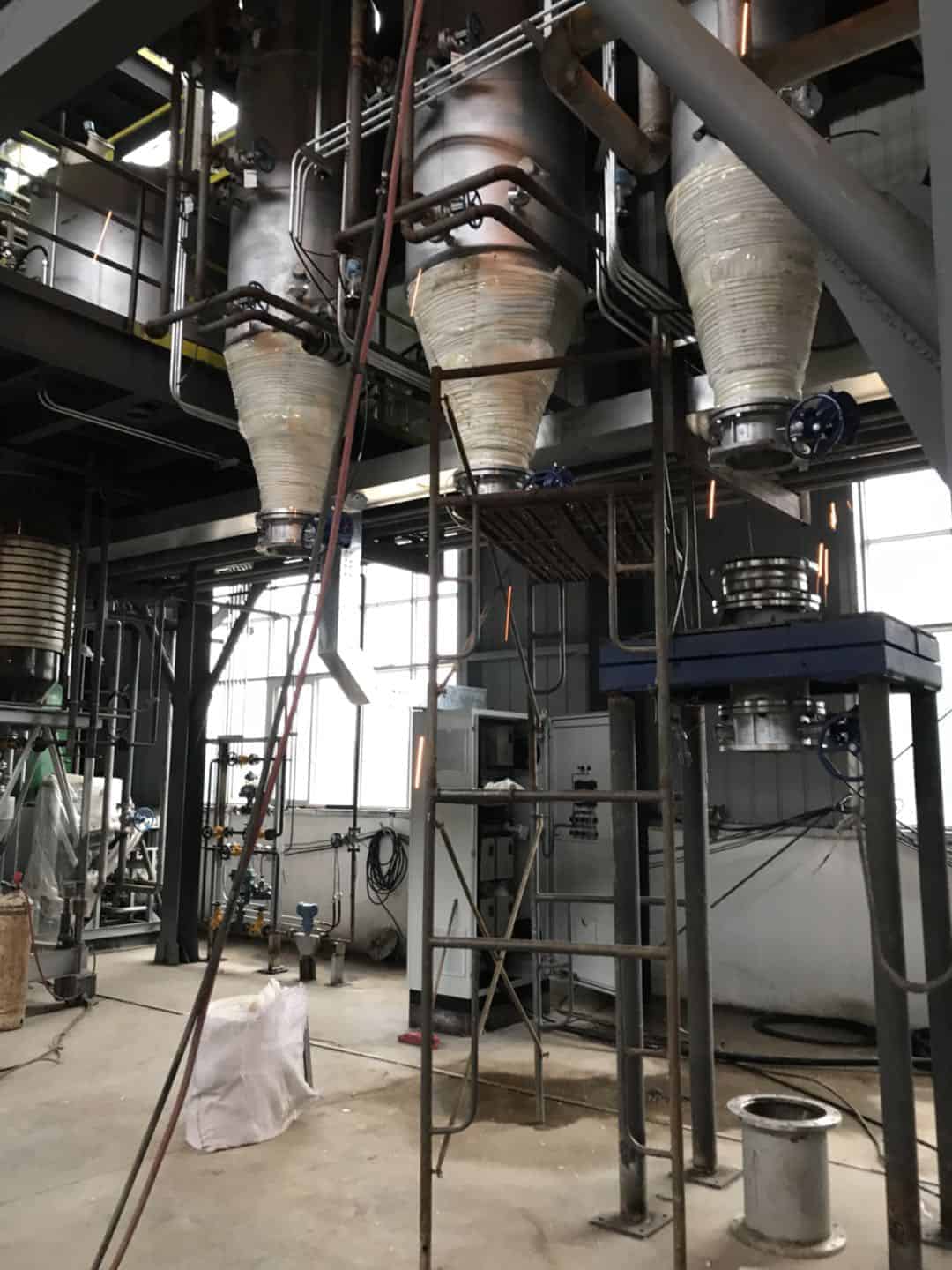
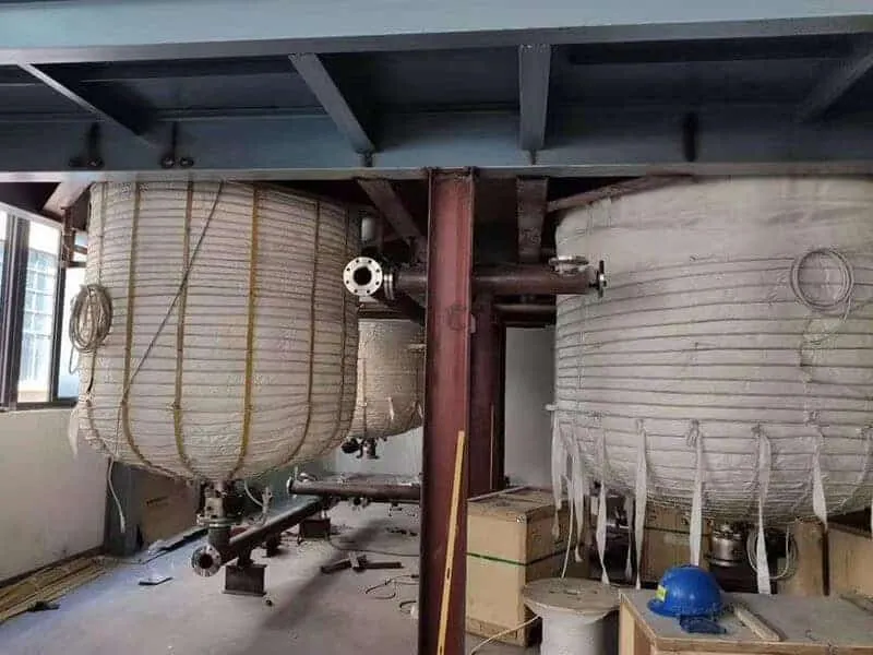
We have over 20 years experience in induction heating and have developed, designed, manufactured, installed and commissioned Vessel and Pipe Heating systems to many countries all over the world. Due to the heating system being naturally simple and very reliable, the option of heating by induction should be regarded as the preferred choice. Induction heating embodies all the conveniences of electricity taken direct to the process and transformed to heat exactly where it is required. It can be applied successfully to virtually any vessel or pipe system needing a source of heat. Induction offers many benefits unobtainable by other means and gives improved plant production efficiency and better operating conditions since there is no significant emission of heat to the surroundings. The system is particularly suitable for close control reaction processes such as the production of synthetic resins in a Hazard Area. As each induction heating vessel is bespoke to each customers specific needs and requirements, we offer varying sizes with differing heat up rates. Our engineers have had many years of experience in evolving custom built induction heating systems for a wide range of applications in a wide range of industries. Heaters are designed to suit the precise requirements of the process and are constructed for quick fitting onto the vessel either in our works or on site.
UNIQUE BENEFITS
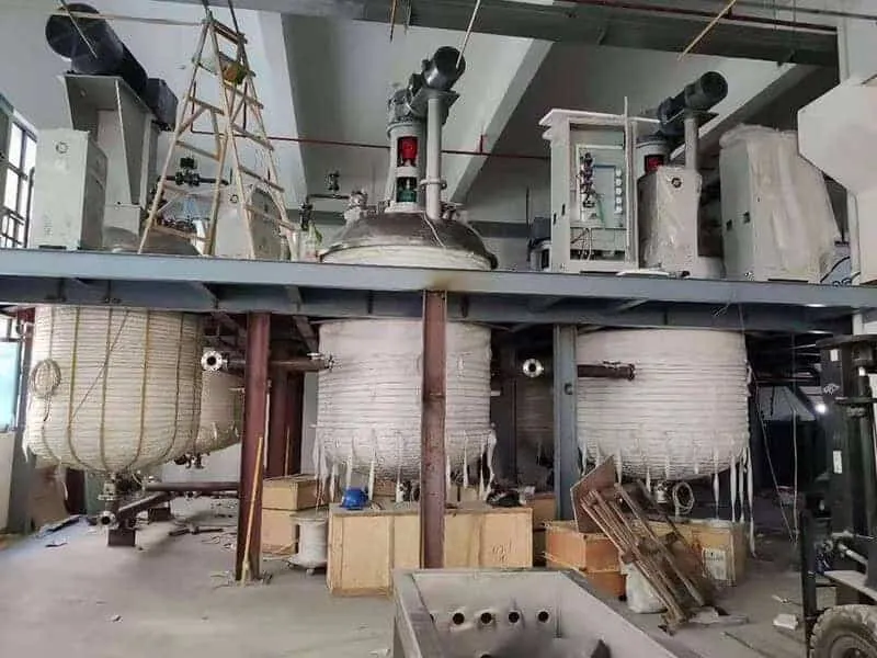
• No physical contact between induction coil and heated vessel wall. • Rapid start-up and shut-down. No thermal inertia. • Low heat loss • Precision product and vessel wall temperature control without over shoot. • High energy input. Ideal for automatic or micro-processor control • Safe hazard area or standard industrial operation at line voltage. • Pollution free uniform heating at high efficiency. • Low running costs. • Low or high temperature working. • Simple and flexible to operate. • Minimum maintenance. • Consistent product quality. • Heater self-contained on vessel generating minimum floor space requirement. Induction heating coil designs are available to suit metallic vessels and tanks of most forms and shapes in current use. Ranging from a few centremetres to several metres diameter or length. Mild steel, clad mild steel, solid stainless steel or non ferrous vessels can all be successfully heated. Generally a minimum wall thickness of 6mm is recommended. Unit rating designs range from 1KW to 1500KW. With induction heating systems there is no limit on power density input. Any limitation that exists is imposed by the maximum heat absorption capacity of the product, process or metallurgical characteristics of the vessel wall material. Induction heating embodies all the conveniences of electricity taken direct to the process and transformed to heat exactly where it is required. Since heating takes place direct in the vessel wall in contact with the product and the heat losses are extremely low, the system is highly efficient (up to 90%). Induction heating offers a great many benefits unobtainable by other means and gives improved plant production efficiency and better operating conditions since there is no significant emission of heat to the surroundings.

Typical industries using induction process heating:
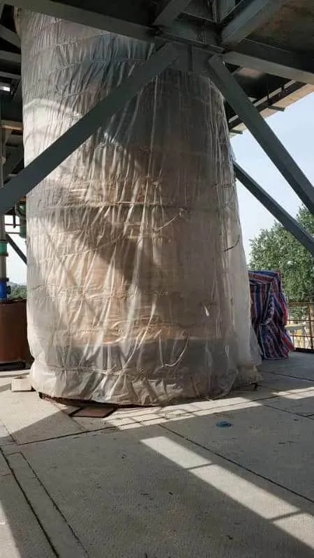
• Reactors and kettles • Adhesive and special coatings • Chemical, gas and oil • Food processing • Metallurgical and metal finishing • Preheating Welding • Coating • Mold heating • Fitting&Unfitting • Thermal Assembly • Food Drying • Pipeline Fluid Heating • Tank & Vessel Heating and Insulation

The HLQ Induction In-Line Heater arrangement can be used for applications include:

• Air and Gas heating for Chemical and Food Processing • Hot Oil Heating for Process and Edible Oils • Vaporising and Superheating: Instant steam raising, low and high temperature / pressure (up to 800ºC at 100 bar)

Previous Vessel and Continuous Heater projects include:
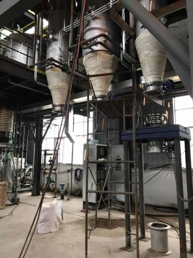
Reactors and Kettles, Autoclaves, Process Vessels, Storage and Settling Tanks, Baths, Vats and Still Pots, Pressure Vessels, Vapourisors and superheaters, Heat Exchangers, Rotary Drums, Pipes, Dual Fuel Heated Vessels

Previous In-Line Heater project include:

High Pressure Super Heated Steam heaters, Regenerative Air Heaters, Lubricating Oil Heaters, Edible Oil and Cooking Oil Heaters, Gas heaters including Nitrogen, Nitrogen Argon and Catalytic Rich Gas (CRG) heaters. Induction heating is a non-contact method of selectively heating electrically-conductive materials by applying an alternating magnetic field to induce an electric current, known as an eddy current, in the material, known as a susceptor, thereby heating the susceptor. Induction heating has been used in the metallurgical industry for many years for the purpose of heating metals, e.g. melting, refining, heat treating, welding, and soldering. Induction heating is practiced over a wide range of frequencies, from AC powerline frequencies as low as 50 Hz up to frequencies of tens of MHz. At a given induction frequency the heating efficiency of the induction field increases when a longer conduction path is present in an object. Large solid work pieces may be heated with lower frequencies, while small objects require higher frequencies. For a given size object to be heated, too low a frequency provides inefficient heating since the energy in the induction field does not generate the desired intensity of eddy currents in the object. Too high a frequency, on the other hand, causes non-uniform heating since the energy in the induction field does not penetrate into the object and eddy currents are only induced at or near the surface. However, induction heating of gas-permeable metallic structures is not known in the prior art. Prior art processes for gas phase catalytic reactions require that the catalyst have a high surface area in order for the reactant gas molecules to have maximum contact with the catalyst surface. The prior art processes typically use either a porous catalyst material or many small catalytic particles, suitably supported, to achieve the required surface area. These prior art processes rely on conduction, radiation or convection to provide the necessary heat to the catalyst. To achieve good selectivity of chemical reaction all portions of the reactants should experience uniform temperature and catalytic environment. For an endothermic reaction, the rate of heat delivery therefore needs to be as uniform as possible over the entire volume of the catalytic bed. Both conduction, and convection, as well as radiation, are inherently limited in their ability to provide the necessary rate and uniformity of heat delivery. GB Patent 2210286 (GB '286), which is typical of the prior art, teaches mounting small catalyst particles that are not electrically conductive on a metallic support or doping the catalyst to render it electrically conductive. The metallic support or the doping material is induction heated and in turn heats the catalyst. This patent teaches the use of a ferromagnetic core passing centrally through the catalyst bed. The preferred material for the ferromagnetic core is silicon iron. Although useful for reactions up to about 600 degrees C., the apparatus of GB Patent 2210286 suffers from severe limitations at higher temperatures. The magnetic permeability of the ferromagnetic core would degrade significantly at higher temperatures. According to Erickson, C. J., “Handbook of Heating for Industry”, pp 84–85, the magnetic permeability of iron starts to degrade at 600 C and is effectively gone by 750 C. Since, in the arrangement of GB '286, the magnetic field in the catalyst bed depends upon the magnetic permeability of the ferromagnetic core, such an arrangement would not effectively heat a catalyst to temperatures in excess of 750 C, let alone reach the greater than 1000 C required for the production of HCN. The apparatus of GB Patent 2210286 is also believed chemically unsuitable for the preparation of HCN. HCN is made by reacting ammonia and a hydrocarbon gas. It is known that iron causes the decomposition of ammonia at elevated temperatures. It is believed that the iron present in the ferromagnetic core and in the catalyst support within the reaction chamber of GB '286 would cause decomposition of the ammonia and would inhibit, rather than promote, the desired reaction of ammonia with a hydrocarbon to form HCN. Hydrogen cyanide (HCN) is an important chemical with many uses in the chemical and mining industries. For example, HCN is a raw material for the manufacture of adiponitrile, acetone cyanohydrin, sodium cyanide, and intermediates in the manufacture of pesticides, agricultural products, chelating agents, and animal feed. HCN is a highly toxic liquid which boils at 26 degrees C., and as such, is subject to stringent packaging and transportation regulations. In some applications, HCN is needed at remote locations distant from large scale HCN manufacturing facilities. Shipment of HCN to such locations involves major hazards. Production of the HCN at sites at which it is to be used would avoid hazards encountered in its transportation, storage, and handling. Small scale on-site production of HCN, using prior art processes, would not be economically feasible. However, small scale, as well as large scale, on-site production of HCN is technically and economically feasible using the processes and apparatus of the present invention. HCN can be produced when compounds containing hydrogen, nitrogen, and carbon are brought together at high temperatures, with or without a catalyst. For example, HCN is typically made by the reaction of ammonia and a hydrocarbon, a reaction which is highly endothermic. The three commercial processes for making HCN are the Blausaure aus Methan und Ammoniak (BMA), the Andrussow, and the Shawinigan processes. These processes can be distinguished by the method of heat generation and transfer, and by whether a catalyst is employed. The Andrussow process uses the heat generated by combustion of a hydrocarbon gas and oxygen within the reactor volume to provide the heat of reaction. The BMA process uses the heat generated by an external combustion process to heat the outer surface of the reactor walls, which in turn heats the inner surface of the reactor walls and thus provides the heat of reaction. The Shawinigan process uses an electric current flowing through electrodes in a fluidized bed to provide the heat of reaction. In the Andrussow process, a mixture of natural gas (a hydrocarbon gas mixture high in methane), ammonia, and oxygen or air are reacted in the presence of a platinum catalyst. The catalyst typically comprises a number of layers of platinum/rhodium wire gauze. The quantity of oxygen is such that the partial combustion of the reactants provides sufficient energy to preheat the reactants to an operating temperature in excess of 1000° C. as well as the required heat of reaction for HCN formation. The reaction products are HCN, H2, H2O, CO, CO2, and trace amounts of higher nitrites, which must then be separated. In the BMA process, a mixture of ammonia and methane flows inside non-porous ceramic tubes made of a high temperature refractory material. The inside of each tube is lined or coated with platinum particles. The tubes are placed in a high temperature furnace and externally heated. The heat is conducted through the ceramic wall to the catalyst surface, which is an integral part of the wall. The reaction is typically carried out at 1300° C. as the reactants contact the catalyst. The heat flux required is high due to the elevated reaction temperature, the large heat of reaction, and the fact that coking of the catalyst surface can occur below the reaction temperature, which deactivates the catalyst. Since each tube is typically about 1″ in diameter, a large number of tubes are needed to meet production requirements. Reaction products are HCN and hydrogen. In the Shawinigan process, the energy required for reaction of a mixture consisting of propane and ammonia is provided by an electric current flowing between electrodes immersed in a fluidized bed of non-catalytic coke particles. The absence of a catalyst, as well as the absence of oxygen or air, in the Shawinigan process means that the reaction must be run at very high temperatures, typically in excess of 1500 degrees C. The higher temperatures required place even greater constraints on the materials of construction for the process. While, as disclosed above, it is known that HCN can be produced by the reaction of NH3 and a hydrocarbon gas, such as CH4 or C3H8, in the presence of a Pt group metal catalyst, there is still a need to improve the efficiency of such processes, and related ones, so as to improve the economics of HCN production, especially for small scale production. It is particularly important to minimize energy use and ammonia breakthrough while maximizing the HCN production rate in comparison to the amount of precious metal catalyst used. Moreover, the catalyst should not detrimentally affect production of HCN by promoting undesirable reactions such as coking. Furthermore, it is desired to improve activity and life of catalysts used in this process. Significantly, a large part of the investment in production of HCN is in the platinum group catalyst. The present invention heats the catalyst directly, rather than indirectly as in the prior art, and thus accomplishes these desiderata. As previously discussed, relatively low frequency induction heating is known to provide good uniformity of heat delivery at high power levels to objects that have relatively long electrical conduction paths. When providing the reaction energy to an endothermic gas phase catalytic reaction, the heat needs to be directly delivered to the catalyst with minimum energy loss. The requirements of uniform and efficient heat delivery to a high-surface-area, gas-permeable catalyst mass seem to conflict with the capabilities of induction heating. The present invention is based on unexpected results obtained with a reactor configuration wherein the catalyst has a novel structural form. This structural form combines the features of: 1) an effectively long electrical conduction path length, which facilitates efficient direct induction heating of the catalyst in a uniform manner, and 2) a catalyst having a high surface area; these features cooperate to facilitate endothermic chemical reactions. The complete lack of iron in the reaction chamber facilitates the production of HCN by the reaction of NH3 and a hydrocarbon gas.  
https://dw-inductionheater.com/induction-heating-reactor-tank-vessels.html?feed_id=235537&_unique_id=65e4e79288b44

induction heating stress relieving

Induction Heating Stress Relieving For metal that has been cold-processed, formed, machined, welded, or cut, it may be necessary to preform a stress relieving operation to reduce stresses created during the fabrication process.

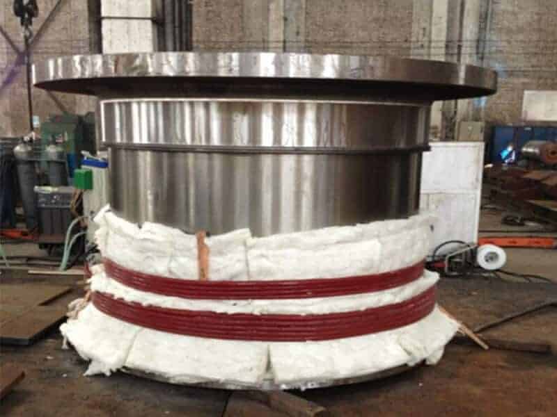
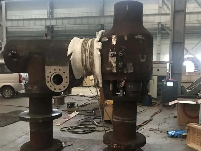
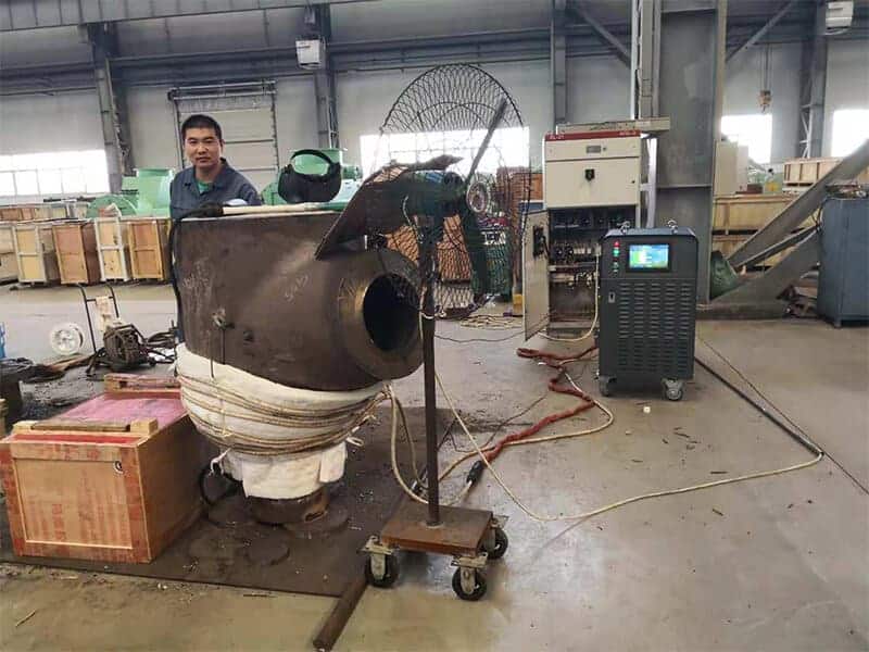
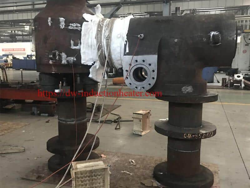
Induction Heating Stress relieving is applied to both ferrous and non-ferrous alloys and is intended to remove internal residual stresses generated by prior manufacturing processes such as machining, cold rolling and welding. Without it, subsequent processing may give rise to unacceptable distortion and/or the material can suffer fromservice problems such as stress corrosion cracking. T he treatment is not intended to produce significant changes in material structures or mechanical properties, and is therefore normally restricted to relatively low temperatures. For metal that has been cold-processed, formed, machined, welded, or cut, it may be necessary to preform a stress relieving operation to reduce stresses created during the fabrication process. Stresses in metal as a result of fabrication operations can cause unwanted dimension changes, distortion, premature failure or stress corrosion cracking of the part when these stresses are released. Parts with tight dimensional requirements may require stress relieved before other production operations can be performed. Welded sections can be made tension-free with a stress relief heating operation. Induction Stress relieving can be performed in a controlled atmosphere chamber or vacuum to reduce oxidation. Carbon steels and alloy steels can be given two forms of stress relief: 1. Treatment at typically 150-200°C relieves peak stresses after hardening without significantly reducing hardness (e.g. case-hardened components, bearings, etc.): 2. Treatment at typically 600-680°C (e.g. after welding, machining etc.) provides virtually complete stress relief. Non-ferrous alloys are stress relieved at a wide variety of temperatures related to alloy type and condition. Alloys that have been age-hardened are restricted to stress relieving temperatures below the ageing temperature. Austenitic stainless steels are stress relieved below 480°C or above 900°C, temperatures in between reducing corrosion resistance in grades that are not stabilised or low-carbon. Treatments above 900°C are often full solution anneals. Normalising Applied to some, but not all, engineering steels, normalising can soften, harden or stress relieve a material, depending on its initial state. The objective of the treatment is to counter the effects of prior processes, such as casting, forging or rolling, by refining the existing non-uniformstructure into one which enhances machinability/formability or, in certain product forms, meets final mechanical property requirements. A primary purpose is to condition a steel so that, after subsequent shaping, a component responds satisfactorily to a hardening operation (e.g. aiding dimensional stability). Normalising consists of heating a suitable steel to a temperature typically in the range 830-950°C (at or above the hardening temperature of hardening steels, or above the carburising temperature for carburising steels) and then cooling in air. Heating is usually carried out in air, so subsequent machining or surface finishing is required to remove scale or decarburised layers. Air-hardening steels (e.g. some automotive gear steels) are often "tempered" (subcritically annealed) after normalising to soften the structure and/or promote machinability. Many aircraft specifications also call for this combination of treatments. Steels that are not usually normalised are those which would harden significantly during air cooling (e.g. many tool steels), or those which gain no structural benefit or produce inappropriate structures or mechanical properties (e.g. the stainless steels). Induction preheating PWHT machine is widely used for pipe/tube weld peheat and pwht, stress reliving and so on. Welding  is one of the most critical processes in the manufacture of pressure vessels like the boiler of a thermal power plant. The temperature of the molten weld pool during the process is in the range of 2000 deg C. The heat increase is rapid and instantaneous. When this small strip of molten pool cools down the shrinkage results in thermal stresses that are locked up inside the metal. This also can change the macrostructure of the steel. PWHT eliminates these effects by heating, soaking, and cooling the weld area in a controlled manner to temperatures below the first transformation point, giving the macro structure sufficient time to readjust to its original state   and removing the residual stress. PWHT consists of heating the metal after the welding process in a controlled   manner to temperature below the first transformation point, soaking at that   temperature for a sufficiently long time, and cooling at controlled rates. Induction heating is one method that is gaining popularity even though the cost is high. This is a more welder friendly process. Unlike resistance heating only the pipe becomes hot. The temperature gradients are uniform across the   thickness. The heating power is from 10KW ~ 120KW Model: 10KW, 20KW, 40KW, 60KW, 80KW, 120KW and so on. Heating temperature: 0 ~ 900 C Max heating temperature: 900 C The pipe / tube diameter: 50 ~ 2000 mm Heating coil: Clamp coil or induction heating blanket The induction weld preheating machine include: 1. induction heating power source. 2. SOFT Induction Heating Cable 3.  Extend cable 4. K type thermocouple 5. Paper / Paperless recorder and so on. Compare with ceramic heater and frame heater. It has more advantage. 1. Quickly heating speed and unfirom heating temperature 2. Energy   saving without any pollution 3. Long working time and more stable 4. Touch screen and PLC control, Easy to operate 5. Can suitable for different welding condition https://dw-inductionheater.com/induction-heating-stress-relieving.html?feed_id=235502&_unique_id=65e430b727979

2024年3月2日星期六

Induction Susceptor Heating

How Induction Susceptor Heating Works?

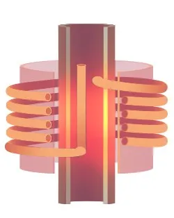
A susceptor is used for the induction heating of non-conductive materials such as ceramics and polymers. The susceptor is heated by an induction heating system, where conduction transfers heat to the work material. Susceptors are often made out of silicon carbide, molybdenum, graphite, stainless steels and a number of other conductive materials. With susceptor heating, we use induction to heat a metal conductive susceptor, which then heats a secondary material either through direct contact conduction or radiation.

What is Induction Susceptor Heating?

Susceptor heating by Induction has been extensively applied to processes where the material to be heated is not electrically conductive or not easily heated evenly with induction heating. Both metallic and non-metallic parts may be heated indirectly with the use of a susceptor, heated by induction. Susceptors may be in contact with or separated from the part or material to be heated. When in contact heating is via conduction, when separated heating is by radiation. The term ‘susceptor’ as used in induction heating denotes an electrically conductive material placed between the induction heating coil and the material to be heated such as a workpiece, either a solid, a slurry, a liquid, a gas, or some combination of the foregoing. In its simplest form, an Induction Susceptor Heater may be a metal tube interposed between the coil and the material to be heated. Such a susceptor is readily heated by the electromagnetic field established by the induction coil so that the part is heated primarily by radiation or conduction from the heated susceptor. Use of a susceptor provides an effective means for heating non-conductive materials like ceramics, glass, plastics, semiconductors, organic and non-organic chemicals, foods, beverages by taking advantage of the control precision, efficiency, rapid ramp-up, and reliability benefits of using an induction heating generator/power supply. HLQ designs and supplies induction susceptor heating equipment from simple tubes through to heated conveyors, augers, and other complicated structures. Susceptors may be designed and employed to protect/shield areas of a part that are not to be subjected to an induction field thus controlling the heat pattern obtained. In some cases, these are referred to as diverters or shields. In such instances, the susceptor covers the portion of the part electromagnetically shielding it. If a susceptor does not completely encircle the part, heating will take place simultaneously by direct induction heating in the unshielded zones as well as by radiation and conduction from the susceptor. In many cases shielding susceptors are constructed of water-cooled copper where the shielded zones of the part are not to be heated at all. Fundamentally, susceptor heating using an induction heating source is simply radiation and/or conduction heating. However, many features make it highly adaptable. Firstly, the susceptor is heated electromagnetically, permitting heating through quartz, glass, or other magnetically transparent chambers for atmosphere containment and control. Secondly, a thin susceptor acts as a radiation source that can be rapidly heated and cooled if desired, creating a heat source that can change temperature very rapidly. Induction heating that susceptor allows for higher reliability due to the fact that the high-temperature susceptor does not have to be connected to a high current conductor to impart the energy required for heating. The susceptor may be of any size. In parts with complex geometry, a susceptor improves the uniformity of heating, as compared to direct induction heating. Susceptors allow for very thin materials such as steel strips or wires to be heated to elevated temperatures using more economical low and medium magnetic field frequencies. When considering a susceptor heating design there are a number of factors that go into selecting the appropriate susceptor material, these include reactivity with the environment that the susceptor is in contact with. Choosing the right material leads to a reliable system, choosing the wrong materials can lead to contamination and low-reliability performance.

Induction Susceptor Heating Applications

Susceptors make induction heating applicable for heating all non-metallic and metallic materials, allowing induction heating to become an important tool in the production of Foods and Beverages, Chemicals, Electronics, Glass, Plastics, Rubber, Construction, Consumer Medical, and industrial products. https://dw-inductionheater.com/induction-susceptor-heating.html?feed_id=235467&_unique_id=65e37a0dc732a

2024年3月1日星期五

Induction Drying Grain with Induction Heating method

Energy savings at the induction drying grain with induction heating method

Annually Kazakhstan produces around 17-19 million tons of grain in clean weight,exports about 5 million tons of grain, and the average volume of domestic consumption reaches 9-11 million tons. Further development of the grain industry and promotion of grain export requires developing the infrastructure of storage, transportation and drying of grain, including the construction of new and reconstruction of the old grain silos, construction of port terminals and purchase of dry cargo vessels and grain carriers (Baum, 1983). There is a need to modernize the industry and the task requires a intensive efforts of the state and national grain producers. Participants of Astana Kazakh Grain Forum V KAZGRAIN-2012 discussed the current state of grain market, trends and price expectations, as well as challenging issues in logistics and infrastructure. It was noted that 10 years ago Kazakhstan could not be considered as a grain exporter, while in current time the export issues are recognized as priority ones. And the production and drying of grain takes one of the leading places both in agroindustrial complex, and the economy as a whole. Analysis of experience of many manufacturing enterprises in post-harvest grain processing proves that the primary task in ensuring the safety and quality of newly harvested seeds is their drying. Importance of grain drying increases in the humid zone: delay in drying or carrying out this operation with violation of technological regimes inevitably cause crop losses. According to the researches in 25-28% humidity of heap for three days the germination decreases by 20%. And the losses of dry matter makes 0.7-1% per day when a moisture of the grain heap is 37% (Ginzburg, 1973). The important factors in efficient use of dryers in agriculture are provision of higher grain quality, increase of bandwidth of units, as well as lowering energy costs. Base for improving the effectiveness of existing dryers in agriculture is ensuring sufficient and stable removal of moisture from one cubic meter in cameras of grain dryers. One of the reason preventing for this is that the cooling units, built into the drying shaft, do not create optimal conditions for full grain cooling and thereby reduce the effective volume of the drying shaft and moisture removal from a cubic meter of the camera. Since the 2010 production of wheat demonstrates a stable growth trend: crop area has increased by 17%, yield has increased by 25%, and total yield - by 52%. In the 1th January in 2012 Kazakhstan had 258 silos with a storage capacity 14 771.3 thousand tons and elevators with storage capacity 14 127.8 thousand tons.  Increase of yield and gross harvest requires improving drying technology to avoid crop losses and maintain grain quality. The most perspective method for grain drying and removing moisture is the induction heating method which remains little studied and rarely used in practice due to considerable imperfections in technologies of  frequency  convertors manufacturing. Though the induction heating equipment production is currently developing and use of it grain drying practice becomes more preferable compared to traditional heating methods (Zhidko, 1982). At present time induction heating is used for surface hardening of steel products, through heating for plastic deformation (forging, stamping, pressing, etc.), metal melting, heat treatment (annealing, tempering, normalizing, quenching), welding, welding, soldering, metals. Indirect induction heating is used for heating of technological equipment (pipelines, tanks, etc.), heating of liquids, drying of coats and materials (e.g., wood). The most important parameter of induction heating installations is frequency. For each process (surface hardening, through heating) there is an optimal frequency range, providing the best technological and  economic performance. Frequencies from 50Hz to 5 MHz are used for induction heating. Advantages of induction heating include the following:
  • Transmission of electrical energy directly into the heating body allows implementing direct heating of materials, thereby the heating rate is
  • Transmission of electrical energy directly into the heating body does not require contact devices. This is useful for automated line
  • When a heating material is a dielectric, e.g. grain, then the power is evenly distributed throughout volume of the heating material. Consequently, this induction method provides fast heating of
  • Induction heating in most cases can increase productivity and improve working conditions. Induction device can be regarded as a kind of transformer, when the primary winding (inductor) is connected to the AC power source, and the heating material serves as the secondary
Reduction of cost of the entire installation requires development and implementation of simple in design induction heaters. The main difference between induction heating from traditional methods of drying lies in volumetric heating. The heat penetrates into the product (material) not from the surface; it is formed in the whole volume at once, this process allows drying grain effectively with low energy consumption. Even distribution of moisture occurs in a dried material during the heating induction process. Induction does not assume heat transfer from heater to a material. While using other methods of drying requires heating the air, then transfer the heat from the hot air to material. At each stage - air heating, its transportation, and heat transfer to products - the heat losses are unavoidable. Nowadays enterprises in Kazakhstan practically do not use induction heaters as they are very expensive. Old lamp models of induction heating machines are outdated and they are not manufactured.

Grain drying by induction heating. Drying in the falling layer 

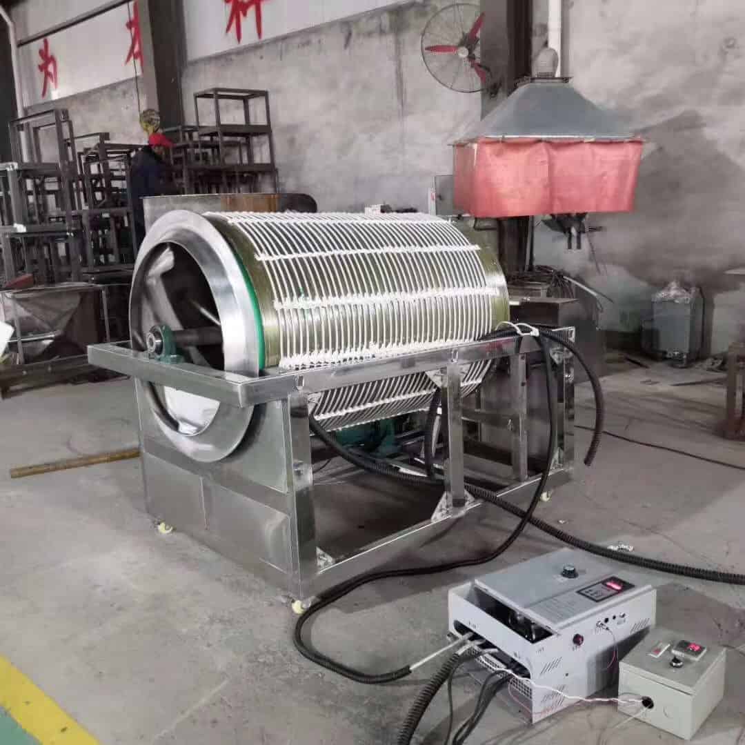
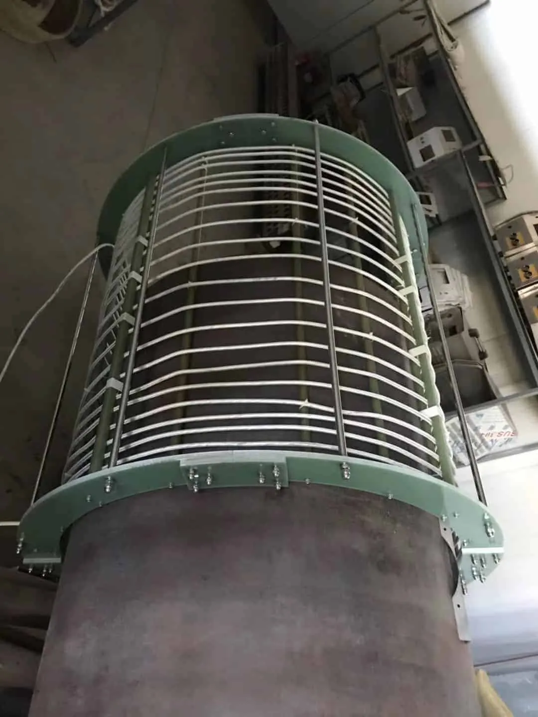
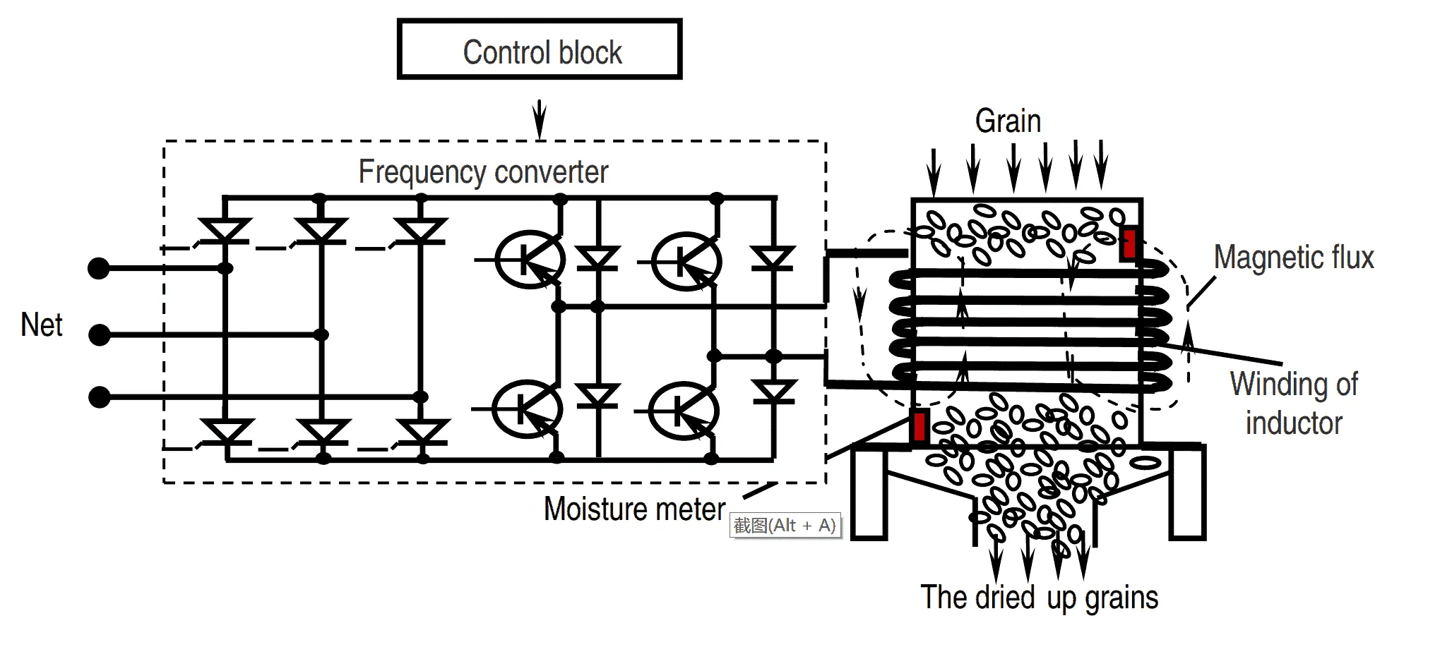
We suggest the induction heating method of grain drying (Figure 1) where the grain material passes, driven by gravity power, through the drying shaft. At the top of the dryer grain is loaded by bucket conveyors or other transport devices; then  grain gets into drying tower. In the camera of drying tower the inductor,  connected to frequency converter, creates electromagnetic field (flux) of high frequency. Drying in falling layer. Falling layer represents highly discharged gravitational moving grain stream, partially offset by upward flow of gas (aerodynamic braking). The true concentration of grain increases in the course of the movement. Drying in suspended layer. The suspended state of grain is achieved in the raising stream of gas when increasing speed of power supply. In the process the whole surface of grain  is involved to heat and moisture exchange with the gas. The time of stay of grain  in the pneumo tube does not exceed few seconds; temperature of drying agent makes 350-400 °C. However, the reduction of moisture amounts to a fraction percent. Therefore, the apparatus with weighted layers of grain are used not as separate dryer, but as an element of multi-chamber combined dryer. Conclusion Today agricultural firms and elevators are equipped mostly by the direct flow shaft dryers. These dryers suggest considerable unevenness in heating and drying of grain, which in turn causes substantial thermal drying costs. The main reason here is the imperfection in supplying the drying agent and atmospheric air to dehydrating layers of grain. An important condition for quality work of grain dryers is an efficient cooling of dried grain. According to plan the cooling devices of grain dryers are designed so that the temperature of the grain at the output should not exceed the atmospheric air temperature by more than 10°C. However, in practice this value reaches more than 12°C when the air temperature is higher than 15°C. Also modern grain dryers provide considerable unevenness in cooling of the individual layers of grain. In the discussed context applying of induction heating drying can be the more suitable way in terms of productivity, quality and cost efficiency.   References  Baum, A., 1983. Grain drying [in Russian], Moscow: Kolos Ginzburg, A., 1973. Essentials of theory and technology in drying of foodstuffs [in Russian], Moscow: Food industry Zhidko, V., 1982. Grain  drying and grain dryers [in Russian], Moscow: Kolos https://dw-inductionheater.com/induction-drying-grain-with-induction-heating-method.html?feed_id=235432&_unique_id=65e2c321661a0

induction hardening steel handheld stamps

induction hardening steel handheld stamps

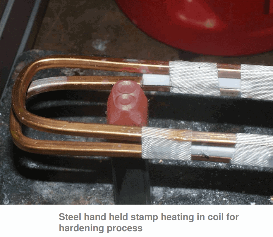
Objective Induction hardening various size ends of handheld marking stamps. The area to be hardened is 3/4” (19mm) up the shank. Material : Steel stamps 1/4” (6.3mm), 3/8” (9.5mm), 1/2” (12.7mm) and 5/8” (15.8mm) square Temperature :1550 ºF (843 ºC) Frequency 99 kHz Equipment • DW-HF-45kW induction heating system, equipped with a remote workhead containing eight 1.0µF capacitors for a total of 2.0µF • An induction heating coil designed and developed specifically for this application. Induction Hardening Process: A two turn channel coil is used to cover the range of steel stamps being heated. The 5/8” steel stamp is heated for 60 seconds to reach 1550 ºF (843 ºC) and the desired hardness. Smaller parts will also heat easily. Results/Benefits Induction heating provides: • Faster process time and production rates • Hands-free heating that involves no operator skill for manufacturing • Controlled precise application of heat https://dw-inductionheater.com/induction-hardening-steel-handheld-stamps.html?feed_id=235397&_unique_id=65e20c4fb4fdb

关注者

我的简介

我的照片
HLQ induction heating machine manufacturer provides the service of induction brazing,melting,hot forming,hardening surface,annealing,shrink fitting,PWHT,etc.