High Frequency Induction Seam Welding Tube and Pipe Solutions
What is induction welding?
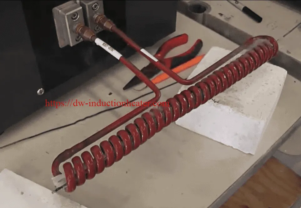
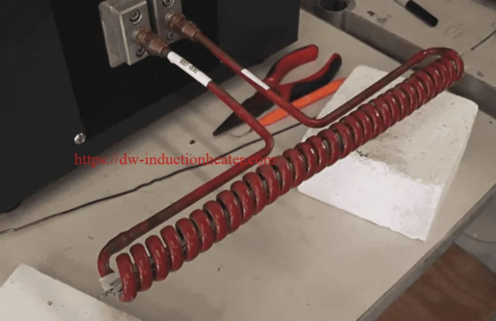
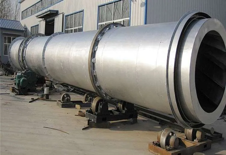
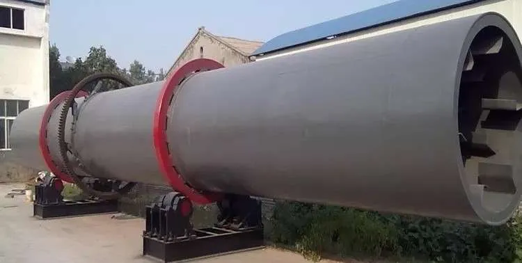
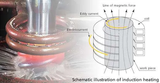
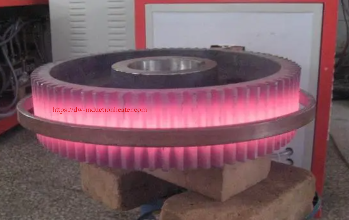
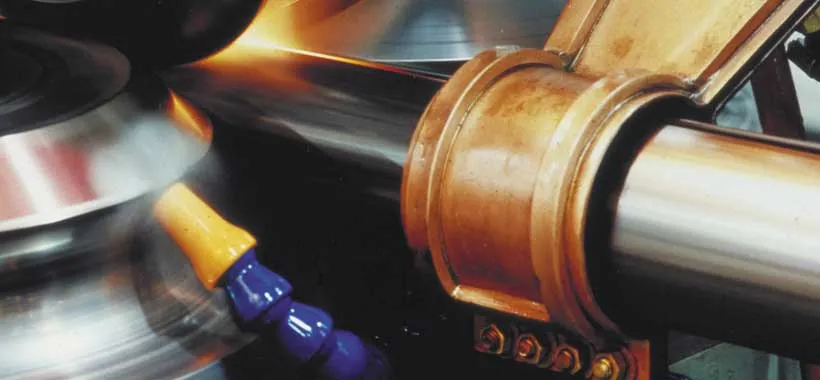
With induction welding, the heat is electromagnetically induced in the workpiece. The speed and accuracy of induction welding makes it ideal for edge welding of tubes and pipes. In this process, pipes pass an induction coil at high speed. As they do so, their edges are heated, then squeezed together to form a longitudinal weld seam. Induction welding is particularly suitable for high-volume production. Induction welders can also be fitted with contact heads, turning them into dual purpose welding systems.
What are the advantages of induction Seam welding?
Automated induction longitudinal welding is a reliable, high-throughput process. The low power consumption and high efficiency of
HLQ Induction welding systems reduce costs. Their controllability and repeatability minimize scrap. Our systems are also flexible—automatic load matching ensures full output power across a wide range of tube sizes. And their small footprint make them easy to integrate or retrofit into production lines.
Where is induction seam welding used?
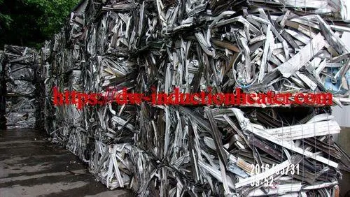
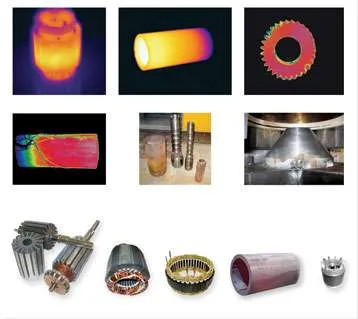
Induction welding is used in the tube and pipe industry for the longitudinal welding of stainless steel (magnetic and non-magnetic), aluminum, low-carbon and high-strength low-alloy (HSLA) steels and many other conductive materials.
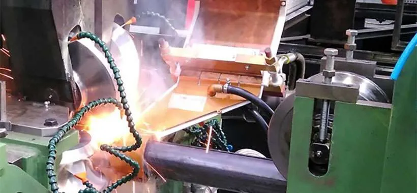
 High Frequency Induction Seam Welding
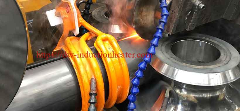
In the high frequency induction tube welding process, high frequency current is induced in the open seam tube by an induction coil located ahead of (upstream from) the weld point, as shown in Fig. 1-1. The tube edges are spaced apart when they go through the coil, forming an open vee whose apex is slightly ahead of the weld point. The coil does not contact the tube.
Fig 1-1
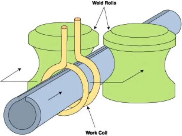
The coil acts as the primary of a high frequency transformer, and the open seam tube acts as a one-turn secondary. As in general induction heating applications, the induced current path in the work piece tends to conform to the shape of the induction coil. Most of the induced current completes its path around the formed strip by flowing along the edges and crowding around the apex of the vee-shaped opening in the strip.
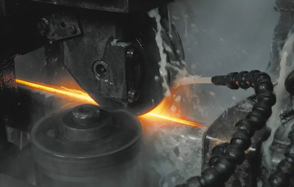
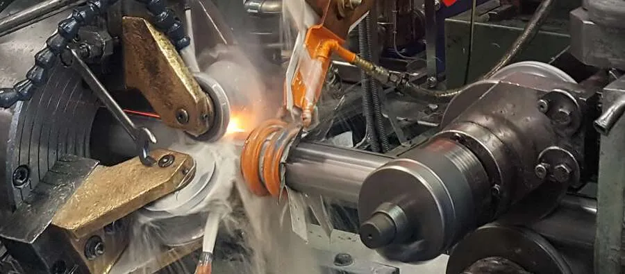
The high frequency current density is highest in the edges near the apex and at the apex itself. Rapid heating takes place, causing the edges to be at welding temperature when they arrive at the apex. Pressure rolls force the heated edges together, completing the weld.
It is the high frequency of the welding current that is responsible for the concentrated heating along the vee edges. It has another advantage, namely that only a very small portion of the total current finds its’ way around the back of the formed strip. Unless the diameter of the tube is very small compared with the vee length, the current prefers the useful path along the edges of the tube forming the vee.
Skin Effect
The HF welding process depends upon two phenomena associated with HF current – Skin Effect and Proximity Effect.
Skin effect is the tendency of HF current to concentrate at the surface of a conductor.
This is illustrated in Fig. 1-3, which shows HF current flowing in isolated conductors of various shapes. Practically the entire current flows in a shallow skin near the surface.
Proximity Effect
The second electrical phenomenon which is important in the HF welding process is proximity effect. This is the tendency of the HF current in a pair of go/return conductors to concentrate in the portions of the conductor surfaces which are nearest each other. This is illustrated in Figs. 1-4 through 1-6 for a round and square conductor cross-sectional shapes and spacings.
The physics behind proximity effect depends on the fact that the magnetic field surrounding the go/return conductors is more concentrated in the narrow space between them than it is elsewhere (Fig. 1-2). The magnetic lines of force have less room and are squeezed closer together. It follows that proximity effect is stronger when the conductors are closer together. It is also stronger when the sides facing each other are wider.
Fig. 1-2
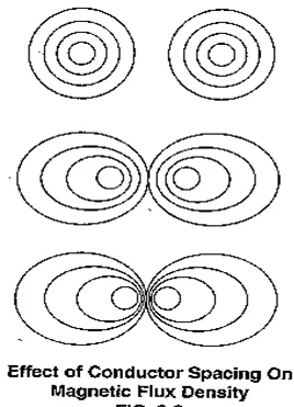
Fig. 1-3
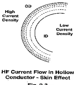
Fig. 1-6 illustrates the effect of tilting two closely spaced rectangular go/return conductors relative to each other. The HF current concentration is greatest in the corners which are nearest together and becomes progressively less along the diverging faces.
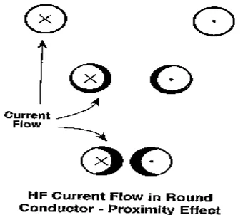
Fig. 1-4
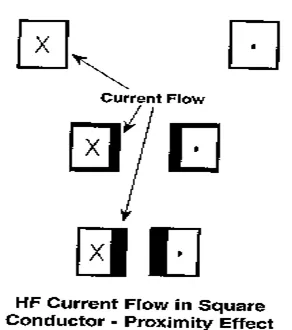
Fig. 1-5
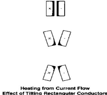
Fig. 1-6
Electrical and Mechanical Interrelationships
There are two general areas which must be optimized in order to get the best electrical conditions:
- The first is to do everything possible to encourage as much of the total HF current as possible to flow in the useful path in the vee.
- The second is to do everything possible to make the edges parallel in the vee so that the heating will be uniform from inside to outside.
Objective (1) clearly depends upon such electrical factors as the design and placement of the welding contacts or coil and on a current impeding device mounted inside the tube. The design is affected by the physical space available on the mill, and the arrangement and size of the weld rolls. If a mandrel is to be used for inside scarfing or rolling, it affects the impeder. In addition, objective (1) depends upon the vee dimensions and angle of opening. Therefore, even though (1) is basically electrical, it ties in closely with the mill mechanicals.
Objective (2) depends wholly upon mechanical factors, such as the shape of the open tube and the edge condition of the strip. These can be affected by what happens back in the mill break-down passes and even at the slitter.
HF welding is an electro-mechanical process: The generator supplies heat to the edges but the squeeze rolls actually make the weld. If the edges are reaching the proper temperature and you still have defective welds, chances are very good that the problem is in the mill set-up or in the material.
Specific Mechanical Factors
In the last analysis, what happens in the vee is all-important. Everything that happens there can have an effect (either good or bad) on weld quality and speed. Some of the factors to be considered in the vee are:
- The vee length
- The degree of opening (vee angle)
- How far ahead of the weld roll centerline the strip edges start to touch each other
- Shape and condition of strip edges in vee
- How the strip edges meet each other – whether simultaneously across their thickness – or first at the outside – or the inside – or through a burr or sliver
- The shape of the formed strip in the vee
- The constancy of all vee dimensions including length, angle of opening, height of edges, thickness of edges
- The position of the welding contacts or coil
- The registration of the strip edges relative to each other when they come together
- How much material is squeezed out (strip width)
- How much oversize the tube or pipe must be for sizing
- How much water or mill coolant is pouring into the vee, and its impingement velocity
- Cleanliness of coolant
- Cleanliness of strip
- Presence of foreign material, such as scale, chips, slivers, inclusions
- Whether steel skelp is from rimmed or killed steel
- Whether welding in rim of rimmed steel or from multiple slit skelp
- Quality of skelp – whether from laminated steel – or steel with excessive stringers and inclusions (“dirty” steel)
- Hardness and physical properties of strip material (which affect amount of spring-back and squeeze pressure required)
- Mill speed uniformity
- Slitting quality
It is obvious that much of what happens in the vee is a result of what has already happened – either in the mill itself or even before the strip or skelp enters the mill.
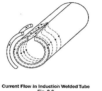
Fig. 1-7
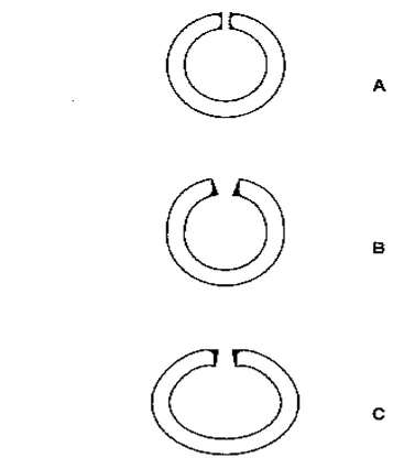
Fig. 1-8
The High Frequency Vee
The purpose of this section is to describe the ideal conditions in the vee. It was shown that parallel edges give uniform heating between inside and outside. Additional reasons for maintaining the edges as parallel as possible will be given in this section. Other vee features, such as the location of the apex, the angle of opening, and the steadiness while running will be discussed.
Later sections will give specific recommendations based on field experience for achieving desirable vee conditions.
Apex as Near Welding Point as Possible
Fig. 2-1 shows the point where the edges meet each other (i.e., the apex) to be somewhat upstream of the pressure roll centerline. This is because a small amount of material is squeezed out during welding. The apex completes the electrical circuit, and the HF current from one edge turns around and goes back along the other.
In the space between the apex and the pressure roll centerline there is no further heating because there is no current flowing, and the heat dissipates rapidly because of the high temperature gradient between the hot edges and the remainder of the tube. Therefore, it is important that the apex be as close as possible to the weld roll centerline in order for the temperature to remain high enough to make a good weld when the pressure is applied.
This rapid heat dissipation is responsible for the fact that when HF power is doubled, the attainable speed more than doubles. The higher speed resulting from the higher power gives less time for heat to be conducted away. A greater part of the heat which is developed electrically in the edges becomes useful, and the efficiency increases.
Degree of Vee Opening
Keeping the apex as close as possible to the weld pressure centerline infers that the opening in the vee should be as wide as possible, but there are practical limits. The first is the physical capability of the mill to hold the edges open without wrinkling or edge damage. The second is the reduction of the proximity effect between the two edges when they are further apart. However, too small of a vee opening may promote pre-arcing and premature closing of the vee causing weld defects.
Based on field experience, the vee opening is generally satisfactory if the space between edges at a point 2.0″ upstream from the weld roll centerline is between 0.080″(2mm) and .200″(5mm) giving an included angle of between 2° and 5° for carbon steel. A larger angle is desirable for stainless steel and non-ferrous metals.
Recommended Vee Opening
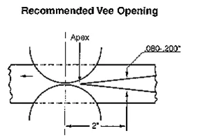
Fig. 2-1
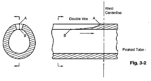
Fig. 2-2
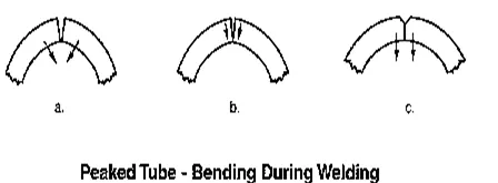
Fig. 2-3
Parallel Edges Avoid Double Vee
Fig. 2-2 illustrates that if the inside edges come together first, there are two vees – one on the outside with its apex at A – the other on the inside with its apex at B. The outside vee is longer and its apex is closer to the pressure roll centerline.
In Fig. 2-2 the HF current prefers the inner vee because the edges are closer together. The current turns around at B. Between B and the weld point, there is no heating and the edges are cooling rapidly. Therefore, it is necessary to overheat the tube by increasing the power or decreasing the speed in order for the temperature at the weld point to be high enough for a satisfactory weld. This is even further worsened because the inside edges will have been heated hotter than the outside.
In extreme cases, the double vee can cause dripping inside and a cold weld outside. This would all be avoided if the edges were parallel.
Parallel Edges Reduce Inclusions
One of the important advantages of HF welding is the fact that a thin skin is melted on the face of the edges. This enables oxides and other undesirable material to be squeezed out, giving a clean, high quality weld. With parallel edges, the oxides are squeezed out in both directions. There is nothing in their way, and they do not have to travel further than half the wall thickness.
If the inside edges come together first, it is harder for the oxides to be squeezed out. In Fig. 2-2 there is a trough between apex A and apex B which acts like a crucible for containing foreign material. This material floats on the melted steel near the hot inside edges. During the time it is being squeezed after passing apex A, it cannot get completely past the cooler outside edges, and can become trapped in the weld interface, forming undesirable inclusions.
There have been many cases where weld defects, due to inclusions near the outside, were traced to the inside edges coming together too soon (i.e., peaked tube). The answer is simply to change the forming so that the edges are parallel. Not to do so may detract the use of one of HF welding’s most important advantages.
Parallel Edges Reduce Relative Motion
Fig. 2-3 shows a series of cross-sections which could have been taken between B and A in Fig. 2-2. When the inside edges of a peaked tube first contact each other, they stick together (Fig. 2-3a). Shortly later (Fig. 2-3b), the portion which is stuck undergoes bending. The outside corners come together as if the edges were hinged at the inside (Fig. 2-3c).
This bending of the inner part of the wall during welding does less harm when welding steel than when welding materials such as aluminum. Steel has a wider plastic temperature range. Preventing relative motion of this sort improves weld quality. This is done by keeping the edges parallel.
Parallel Edges Reduce Welding Time
Again referring to Fig. 2-3, the welding process is taking place all the way from B to the weld roll centerline. It is at this centerline that the maximum pressure is finally exerted and the weld is completed.
In contrast, when the edges come together parallel, they do not start to touch until they at least reach Point A. Almost immediately, the maximum pressure is applied. Parallel edges may reduce the welding time by as much as 2.5 to 1 or more.
Bringing the edges together parallel utilizes what blacksmiths have always known: Strike while the iron is hot!
The Vee as an Electrical Load on Generator
In the HF process, when impeders and seam guides are used as recommended, the useful path along the vee edges comprises the total load circuit which is placed on the high frequency generator. The current drawn from the generator by the vee depends upon the electrical impedance of the vee. This impedance, in turn, depends upon the vee dimensions. As the vee is lengthened (contacts or coil moved back), the impedance increases, and the current tends to be reduced. Also, the reduced current must now heat more metal (because of the longer vee), therefore, more power is needed to bring the weld area back to the welding temperature. As the wall thickness is increased, the impedance decreases, and the current tends to increase. It is necessary for the impedance of the vee to be reasonably close to the design value if full power is to be drawn from the high frequency generator. Like the filament in a light bulb, the power drawn depends upon the resistance and the applied voltage, not upon the size of the generating station.
For electrical reasons, therefore, especially when full HF generator output is desired, it is necessary that the vee dimensions are as recommended.
Forming Tooling
Forming Affects Weld Quality
As already explained, the success of HF welding depends on whether the forming section delivers steady, sliver-free, and parallel edges to the vee. We do not attempt to recommend detailed tooling for every make and size of mill, but we do suggest some ideas regarding general principles. When the reasons are understood, the rest is a straight-forward job for roll designers. Correct forming tooling improves weld quality and also makes the operator’s job easier.
Edge Breaking Recommended
We recommend either straight or modified edge breaking. This gives the top of the tube its final radius in the first one or two passes. Sometimes thin wall tube is over-formed to allow for springback. The fin passes should preferably not be relied upon to form this radius. They cannot overform without damaging the edges such that they do not come out parallel. The reason for this recommendation is so that the edges will be parallel before they get to the weld rolls – i.e., in the vee. This differs from usual ERW practice, where large circular electrodes must act as high current contacting devices and at the same time as rolls to form the edges down.
Edge Break versus Center Break
Proponents of center breaking say that center-break rolls can handle a range of sizes, which reduces tooling inventory and cuts roll change downtime. This is a valid economic argument with a big mill where the rolls are large and expensive. However, this advantage is partly offset because they often need side rolls or a series of flat rolls after the last fin pass to keep the edges down. Up to at least 6 or 8″ OD, edge breaking is more advantageous.
This is true in spite of the fact that it is desirable to use different top breakdown rolls for thick walls than for thin walls. Fig. 3-1a illustrates that a top roll designed for thin wall does not allow enough room at the sides for the thicker walls. If you try to get around this by using a top roll which is narrow enough for the thickest strip over a wide range of thicknesses, you’ll be in trouble at the thin end of the range as suggested in Fig. 3-1b. The sides of the strip will not be contained and edge breaking will not be complete. This causes the seam to roll from side to side in the weld rolls – highly undesirable for good welding.
Another method which is sometimes used but which we do not recommend for small mills, is to use a built-up bottom roll with spacers in the center. A thinner center spacer and a thicker back spacer are used when running thin wall. Roll design for this method is a compromise at best. Fig. 3-1c shows what happens when the top roll is designed for thick wall and the bottom roll is narrowed by substituting spacers so as to run thin wall. The strip is pinched near the edges but is loose at the center. This tends to cause instability along the mill, including the welding vee.
Another argument is that edge breaking can cause buckling. This is not so when the transition section is correctly tooled and adjusted and the forming is properly distributed along the mill.
Recent developments in computer controlled cage forming technology assures flat, parallel edges and rapid change-over times.
In our experience, the added effort to use proper edge breaking pays well in reliable, consistent, easy to operate, high quality production.
Fin Passes Compatible
The progression in the fin passes should lead smoothly into the last fin pass shape recommended previously. Each fin pass should do approximately the same amount of work. This avoids damaging the edges in an overworked fin pass.
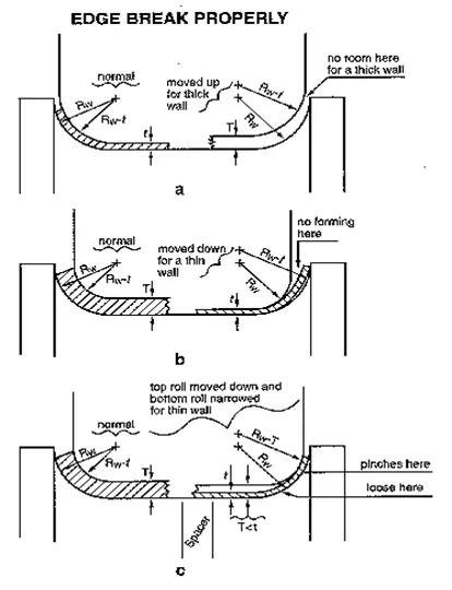
Fig. 3-1
Weld Rolls
Weld Rolls and Last Fin Rolls Correlated
Getting parallel edges in the vee requires correlation of the design of the last fin pass rolls and of the weld rolls. The seam guide along with any side rolls which may be used in this area are for guiding only. This section describes some weld roll designs which have given excellent results in many installations and describes a last finpass design to match these weld roll designs.
The only function of the weld rolls in HF welding is to force the heated edges together with enough pressure to make a good weld. The fin roll design should deliver the skelp completely formed (including radius near edges), but open at the top to the weld rolls. The opening is obtained as if a completely closed tube had been made of two halves connected by a piano hinge at the bottom and simply swung apart at the top (Fig. 4-1). This fin roll design accomplishes this without any undesirable concavity at the bottom.
Two-Roll Arrangement
The weld rolls must be capable of closing the tube with enough pressure to upset the edges even with the welder shut off and the edges cold. This requires large horizontal components of force as suggested by the arrows in Fig. 4-1. A simple, straightforward way of getting these forces is to use two side rolls as suggested in Fig. 4-2.
A two-roll box is relatively economical to build. There is only one screw to adjust during a run. It has right and left hand threads, and moves the two rolls in and out together. This arrangement is in widespread use for small diameters and thin walls. The two-roll construction has the important advantage that it enables the use of the flat oval weld roll throat shape which was developed by THERMATOOL to help assure that the tube edges are parallel.
Under some circumstances the two-roll arrangement may be prone to causing swirl marks on the tube. A common reason for this is improper forming, requiring the roll edges to exert higher than normal pressure. Swirl marks may also occur with high strength materials, which require high weld pressure. Frequent cleaning of the roll edges with a flapper wheel or grinder will help to minimize the marking.
Grinding the rolls while in motion will minimize the possibility of over grinding or nicking the roll but extreme caution should be exercised when doing so. Always have someone standing by the E-Stop in case of an emergency.
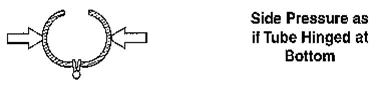
Fig. 4-1
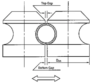
Fig. 4-2
Three-Roll Arrangement
Many mill operators prefer the three-roll arrangement shown in Fig. 4-3 for small tube (up to about 4-1/2″O.D.). Its major advantage over the two-roll arrangement is that swirl marks are virtually eliminated. It also provides adjustment for correcting edge registration should this be necessary.
The three rolls, spaced 120 degrees apart, are mounted in clevises on a heavy duty three-jaw scroll chuck. They can be adjusted in and out together by the chuck screw. The chuck is mounted on a sturdy, adjustable back plate. The first adjustment is made with the three rolls closed tightly on a machined plug. The back plate is adjusted vertically and laterally so as to bring the bottom roll into precise alignment with the mill pass height and with the mill centerline. Then the back plate is locked securely and needs no further adjusting until the next roll change.
The clevises holding the two upper rolls are mounted in radial slides provided with adjusting screws. Either of these two rolls can be adjusted individually. This is in addition to the common adjustment of the three rolls together by the scroll chuck.
Two Rolls – Roll Design
For tube less than about 1.0 OD, and a two-roll box, the recommended shape is shown in Fig. 4-4. This is the optimum shape. It gives the best weld quality and highest weld speed. Above about 1.0 OD, the .020 offset becomes insignificant and may be omitted, each roll being ground from a common center.
Three Rolls – Roll Design
Three-roll weld throats are usually ground round, with a diameter DW equal to the finished tube diameter D plus the sizing allowance a
RW = DW/2
As with the two-roll box, use Fig. 4-5 as a guide for choosing the roll diameter. The top gap should be .050 or equal to the thinnest wall to be run, whichever is greater. The other two gaps should be .060 maximum, scaled to as low as .020 for very thin walls. The same recommendation regarding precision that was made for the two-roll box applies here.
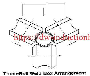
Fig. 4-3
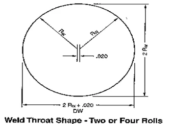
Fig. 4-4
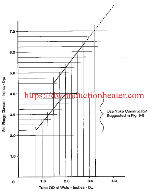
Fig. 4-5
THE LAST FIN PASS
Design Objectives
The shape recommended for the last fin pass was chosen with a number of objectives:
- To present the tube to the weld rolls with the edge radius formed
- To have parallel edges through the vee
- To provide satisfactory vee opening
- To be compatible with the weld roll design recommended previously
- To be simple to grind.
Last Fin Pass Shape
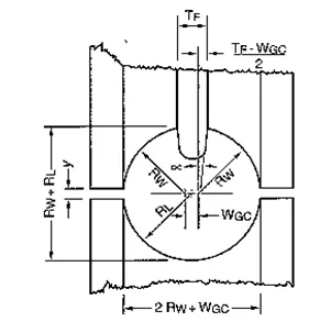
The recommended shape is illustrated in Fig. 4-6. The bottom roll has a constant radius from a single center. Each of the two top roll halves also has a constant radius. However, the top roll radius RW is not equal to the lower roll radius RL and the centers from which the top radii are ground are displaced laterally by a distance WGC. The fin itself is tapered at an angle.
Design Criteria
The dimensions are fixed by the following five criteria:
- The top grinding radii are the same as the weld roll grinding radius RW.
- The girth GF is larger than the girth GW in the weld rolls by an amount equal to the squeeze out allowance S.
- The fin thickness TF is such that the opening between edges will be in accordance with Fig. 2-1.
- The fin taper angle a is such that the tube edges will be perpendicular to the tangent.
- The space y between upper and lower roll flanges is chosen to contain the strip without marking while at the same time providing some degree of operating adjustment.
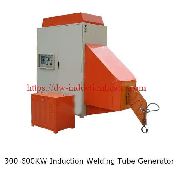
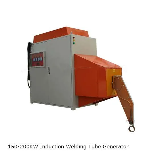
 Technical Features Of High Frequency Induction Seam Welding Generator:
| All Solid State (MOSFET) High Frequency Induction Tube and Pipe Welding Machine |
| Model |
GPWP-60 |
GPWP-100 |
GPWP-150 |
GPWP-200 |
GPWP-250 |
GPWP-300 |
| Input power |
60KW |
100KW |
150KW |
200KW |
250KW |
300KW |
| Input voltage |
3Phases,380/400/480V |
| DC Voltage |
0-250V |
| DC Current |
0-300A |
0-500A |
800A |
1000A |
1250A |
1500A |
| Frequency |
200-500KHz |
| Output efficiency |
85%-95% |
| Power factor |
Full load>0.88 |
| Cooling Water Pressure |
>0.3MPa |
| Cooling Water Flow |
>60L/min |
>83L/min |
>114L/min |
>114L/min |
>160L/min |
>160L/min |
| Inlet water temperature |
<35°C |
 True all-solid-state IGBT power adjustment and variable current control technology, using unique IGBT soft-switching high-frequency chopping and amorphous filtering for power regulation, high-speed and precise soft-switching IGBT inverter control, to achieve 100-800KHZ/3 -300KW product application.
- Imported high-power resonant capacitors are used to obtain stable resonant frequency, effectively improve product quality, and realize the stability of the welded pipe process.
- Replace the traditional thyristor power adjustment technology with high-frequency chopping power adjustment technology to achieve microsecond level control, greatly realize the rapid adjustment and stability of the power output of the welding pipe process, the output ripple is extremely small, and the oscillation current is stable. The smoothness and straightness of the weld seam are guaranteed.
- Security. There is no high frequency and high voltage of 10,000 volts in the equipment, which can effectively avoid radiation, interference, discharge, ignition and other phenomena.
- It has a strong ability to resist network voltage fluctuations.
- It has a high power factor in the whole power range, which can effectively save energy.
- High efficiency and energy saving. The equipment adopts high-power soft switching technology from input to output, which minimizes power loss and obtains extremely high electrical efficiency, and has extremely high power factor in the full power range, effectively saving energy, which is different from traditional Compared with the tube type high frequency, it can save 30-40% of the energy saving effect.
- The equipment is miniaturized and integrated, which greatly saves the occupied space. The equipment does not need a step-down transformer, and does not need a power frequency large inductance for SCR adjustment. The small integrated structure brings convenience in installation, maintenance, transportation, and adjustment.
- The frequency range of 200-500KHZ realizes the welding of steel and stainless steel pipes.
 High Frequency Induction Tube and Pipe Welding Solutions
https://dw-inductionheater.com/induction-seam-welding-for-tube-and-pipe.html?feed_id=209386&_unique_id=64775a299ffef
High Frequency Induction Tube and Pipe Welding Solutions
https://dw-inductionheater.com/induction-seam-welding-for-tube-and-pipe.html?feed_id=209386&_unique_id=64775a299ffef

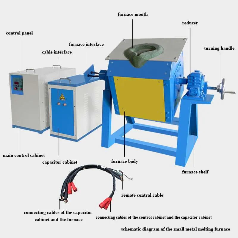
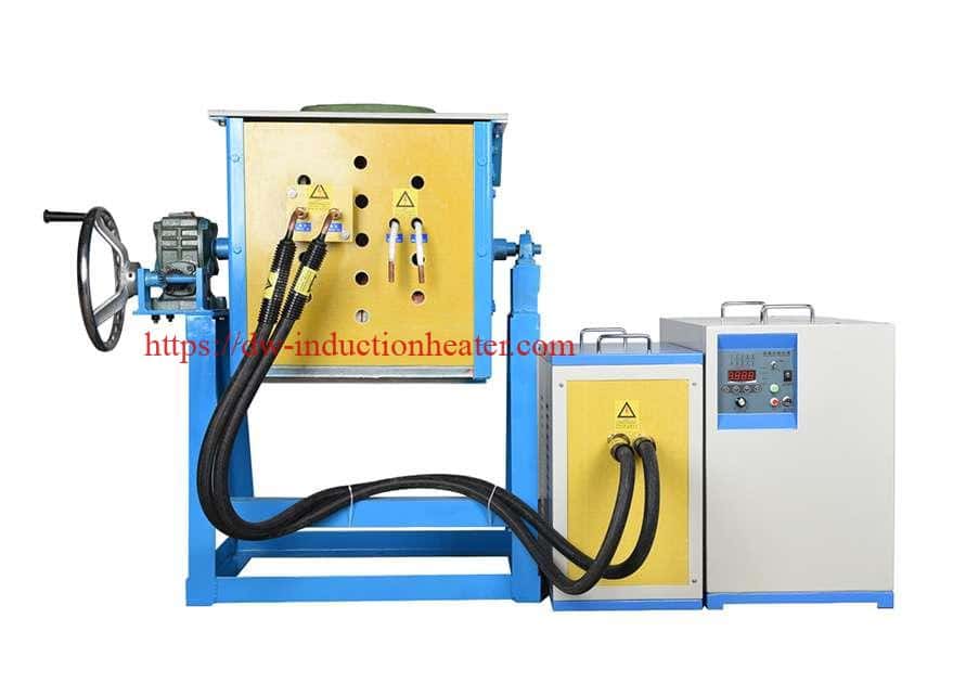
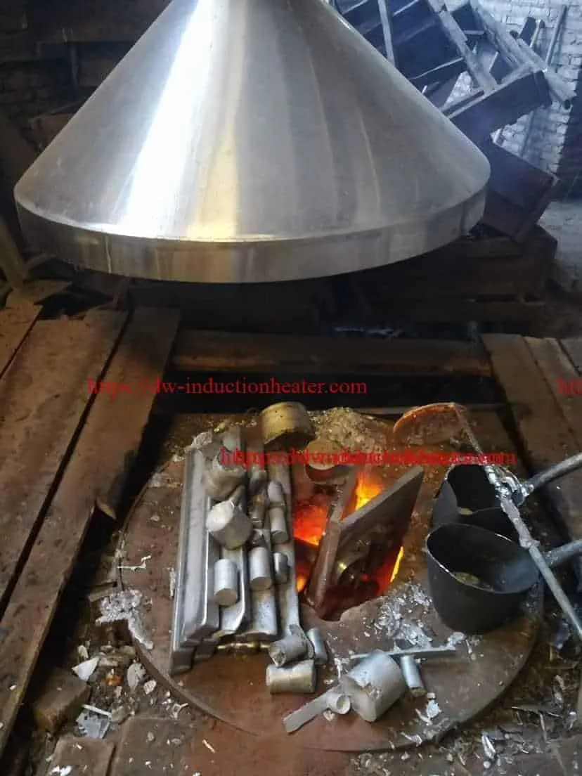
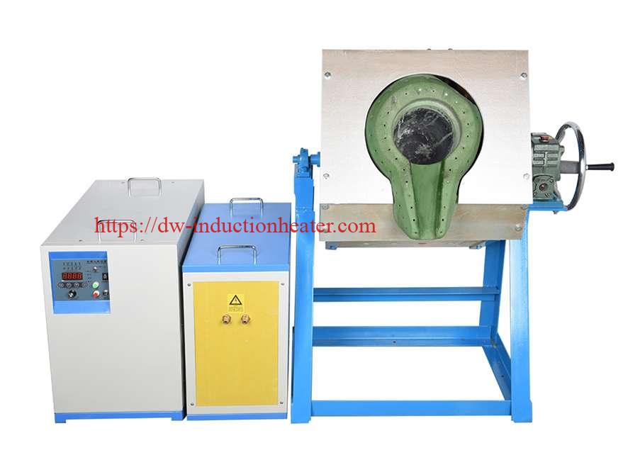 Main Features of MF induction melting furnace
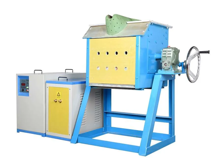 https://dw-inductionheater.com/induction-melting-furnace-with-manual-tilting-device.html?feed_id=209536&_unique_id=64783b9216adb