2021年10月29日星期五

Induction Aluminum Brazing with Computer Assisted

Induction Aluminum Brazing with Computer Assisted

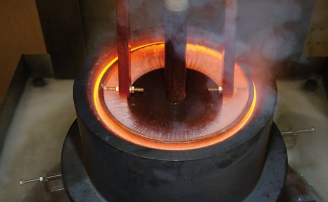
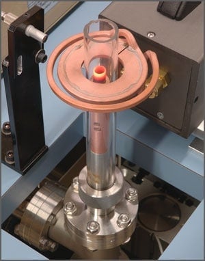
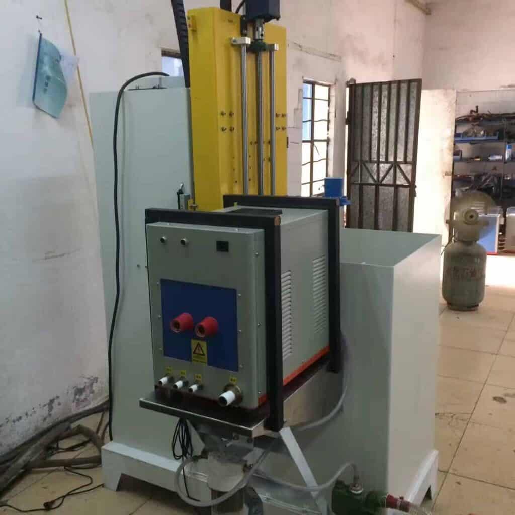
Induction aluminum brazing is becoming more and more common in industry. A typical example is brazing various pipes to an automotive heat  exchanger  body. The induction heating coil widely used for this type of process is non-encircling one, which can be referred to as “Horseshoe-hairpin” style. For these coils, the magnetic field and resulting eddy current distribution are inherently 3-D in nature. In these applications, there are problems with joint quality and consistency of the results from part to part. To solve one such problem for a large automotive manufacturer, Flux3D computer simulation program was used for the process study  and optimization. Optimization included changing the induction coil and magnetic flux controller configuration. New induction coils, which have been experimentally validated in a laboratory, produce parts with higher quality joints in several production sites. Each car requires several different heat exchangers (heater cores, evaporators, condensers, radiators, etc.) for powertrain cooling, air conditioning, oil cooling,  etc. The vast majority of the passenger car heat exchangers today are made of aluminum or aluminum alloys. Even  if the same engine is used for several automobile  models, the connections can vary due to different layouts under the hood. For this reason, it is standard practice  for parts manufacturers to make several basic heat exchanger bodies and then attach different connectors in a secondary operation. Heat exchanger bodies usually consist of aluminum fins, tubes and headers brazed together in a furnace. After brazing, heat exchangers are customized for the given  car model by attaching either nylon tanks or most commonly  different  aluminum  pipes  with   connection blocks. These pipes are attached either by MIG welding, flame or induction brazing. In the case of brazing, very precise temperature control is required due to the small difference in the melting and brazing temperatures for aluminum (20-50 C depending upon alloy, filler metal and atmosphere), high thermal conductivity of aluminum and short distance to other joints brazed in a previous operation. Induction heating is a common method for brazing various pipes to heat exchanger headers. Figure 1 is a picture of an induction brazing set-up for brazing a pipe to a tube on a heat exchanger header. Due to the requirements for precise heating, the face of the induction coil must be in close proximity to the joint to be brazed. Therefore a simple cylindrical coil can not be used, because the part could not be removed after the joint is brazed. There are two main induction coil styles used for brazing these joints: “clamshell” and “horseshoe-hairpin” style inductors. “Clamshell” inductors are similar  to cylindrical inductors, but they open to allow part removal. “Horseshoe-hairpin” inductors are shaped like  a horseshoe for loading the part and are essentially two hairpin coils on opposite sides of the joint. The advantage of using a “Clamshell” inductor is that  the heating is more uniform in circumference and relatively easy to predict. The disadvantage of a “Clamshell” inductor is that the mechanical system required is more complicated and the high current contacts are relatively unreliable. “Horseshoe-hairpin” inductors produce more complicated 3-D heat patterns than “Clamshells”. The advantage of a “Horseshoe-hairpin” style inductor is that the part handling is simplified. [caption id="attachment_6409" align="alignnone" width="1024"] Induction Aluminum Brazing[/caption]

Computer simulation optimizes brazing

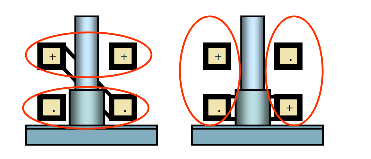
A large heat-exchanger manufacturer was having quality problems with brazing the joint shown in Fig. 1 using a horseshoe-hairpin style inductor. The braze joint was good for the majority of parts, but heating would be totally different for some parts, resulting in insufficient joint depth, cold joints and filler metal running up the pipe wall due to local overheating. Even with testing of each heat exchanger for leaks, some parts still leaked at this joint in service. Centre for Induction Technology Inc. was contracted to analyze and solve the problem. The power supply used for the job has a variable frequency of 10 to 25 kHz and rated power of 60 kW. In the brazing process, an operator installs a filler metal ring on the pipe end and inserts the pipe inside the tube. A heat exchanger is placed onto a special rig and moved inside the horseshoe inductor. The entire brazing area is prefluxed. The frequency used to heat up the part typically is 12 to 15 kHz, and heating time is around 20 seconds. The power level is programmed with linear reduction at the end of the heating cycle. An optical pyrometer turns off the power when the temperature on the back side of the joint reaches a preset value. There are many factors that can cause the inconsistency the manufacturer was experiencing, such as variation in joint components (dimensions and position) and unstable and variable (in time) electrical and thermal contact between the tube, pipe, filler ring, etc. Some phenomena are inherently unstable, and small variations of these factors can cause different process dynamics. For example, the open filler metal ring can partially unwind under the electromagnetic forces, and the free end of the ring may be sucked back by capillary forces or remained unmelted. The noise factors are difficult to reduce or eliminate, and the solution to the problem required increasing the robustness of the total process. Computer simulation is an effective tool to analyze and optimize the process. During the evaluation of the brazing process, strong electrodynamic forces were observed. At the moment the power is turned on, the horseshoe coil clearly experiences an expansion due to a sudden application of electrodynamic force. Thus, the inductor was made mechanically stronger, including incorporating an additional fiberglass (G10) plate connecting the roots of two hairpin coils. The other demonstration of electrodynamic forces present was the shifting of molten filler metal away from the areas close to copper turns where the magnetic field is stronger. In a normal process, filler metal distributes uniformly around the joint due to capillary forces and gravity in contrast to an abnormal process where filler metal may run out of the joint or move up along the pipe surface. Because induction aluminum brazing is a very complicated process, it is not feasible to expect an accurate simulation of the whole chain of mutually coupled phenomena (electromagnetic, thermal, mechanical, hydrodynamic and metallurgical). The most important and controllable process is the generation of electromagnetic heat sources, which were analyzed using the Flux 3D program. Due to the complex nature of the induction brazing process, a combination of computer simulation and experiments was used for process design and optimization.   Induction_Aluminum_Brazing with Computer_Assisted

Induction Bearing Heater

Induction bearing heater is an advanced, fast and controllable heating tool, as opposed to the traditional oven, heat oil or guns heating methods, induction heating is safer, more environmentally-friendly methods of heating.

Feature 1)Adopt the most advanced chip micro processing technology, strong and durable design for continuous  working  condition provides a safe and reliable guarantee 2)Will the microcomputer control technology applied in heating control process, so as to realize the  heater soft start,  soft stop, automatic adjust the output power, automatic detection procedures, self heating device failure,  and  abnormal working state diagnosis and protection function 3)Heating temperature and time can be preset and display, cylindrical peng expansion, the hole is  changeless,  can become a production line of a processing link, significantly save production cost 4)Special design in lower consumption provide higher effect, to save energy.

Technical Specification

Model

ELDC-1

ELDC-3.6

ELDX-8

ELDX-12

ELDX-24

ELDC-24

ELDC-40

ELDC-95

Electric

power (KW)

1

3.6

8

12

24

24

40

95

Voltage(V)

220

220

380

380

380

380

380

380

Frequency(HZ)

50

50

50

50

50

50

50

50

electric current(A)

6

16

20

30

60

60

100

240

Bearing Weight(Kg)

10

35

75

150

250

350

750

Customized

Inside Diameter(mm)

15

28

35

45

85

85

85

145

Outside Diameter(mm)

150

340

480

700

700

900

1400

2500

Width(mm)

60

140

210

310

320

400

420

700

Tallest Temperature

270°C

270°C

270°C

270°C

270°C

270°C

270°C

270°C

Heating rod size

10,20,40

20,45,60

30,40,50,70

30,40,60,80

40,60,80

60,80,100

60,80,100,150

100,150,200,240

Weight

10

29

53

120

175

200

660

2350

[pdf-embedder url="https://dw-inductionheater.com/wp-content/uploads/2018/09/HLQ-Brochure.pdf"]

Induction Hardening Surface Process

Induction Hardening Surface Process Applicatons

What is induction hardening ?

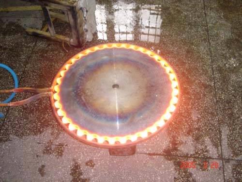
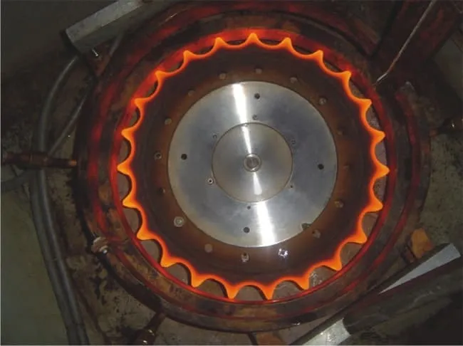
Induction hardening is a form of heat treatment in which a metal part with sufficient carbon content is heated in the induction field and then rapidly cooled. This increases both the hardness and brittleness of the part. Induction heating allows you to have localized heating to a pre-determined temperature and enables you to precisely control the hardening process. Process repeatability is thus guaranteed. Usually, induction hardening is applied to metal parts which need to have great surface wear resistance, while at the same time retaining their mechanical properties. After the induction hardening process is achieved, the metal workpiece needs to be quenched in water, oil or air inorder to obtain specific properties of the surface layer. induction hardening surface process Induction hardening is a method of quickly and selectively hardening the surface of a metal part. A copper coil carrying a significant level of alternating current is placed near (not touching) the part. Heat is generated at, and near the surface by eddy current and hysteresis losses. Quench, usually water-based with an addition such as a polymer, is directed at the part or it is submerged. This transforms the structure to martensite, which is much harder than the prior structure. A popular, modern type of induction hardening equipment is called a scanner. The part is held between centers, rotated, and passed through a progressive coil which provides both heat and quench. The quench is directed below the coil, so any given area of the part is rapidly cooled immediately following heating. Power level, dwell time, scan (feed) rate and other process variables are precisely controlled by a computer. Case hardening process used to increase wear resistance, surface hardness and fatigue life through creation of a hardened surface layer while maintaining an unaffected core microstructure.
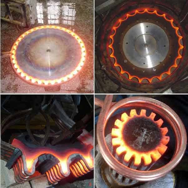
Induction hardening is used to increase the mechanical properties of ferrous components in a specific area. Typical applications are powertrain, suspension, engine components and stampings. Induction hardening is excellent at repairing warranty claims / field failures. The primary benefits are improvements in strength, fatigue and wear resistance in a localised area without having to redesign the component.

Processes and Industries that can benefit from induction hardening:

  • Heat-treatment
  • Chain hardening
  • Tube & Pipe Hardening
  • Shipbuilding
  • Aerospace
  • Railway
  • Automotive
  • Renewable energies

Benefits of Induction Hardening:

Favoured for components that are subjected to heavy loading. Induction imparts a high surface hardness with a deep case capable of handling extremely high loads. Fatigue strength is increased by the development of a soft core surrounded by an extremely tough outer layer. These properties are desirable for parts that experience torsional loading and surfaces that experience impact forces. Induction processing is performed one part at a time allowing for very predictable dimensional movement from part to part.
  • Precise control over temperature and hardening depth
  • Controlled and localized heating
  • Easily integrated into production lines
  • Fast and repeatable process
  • Each workpiece can be hardened by precise optimized parameters
  • Energy-efficient process
Steel and stainless-steel components that can be hardened with induction: Fasteners, flanges, gears, bearings, tube, inner and outer races, crankshafts, camshafts, yokes, drive shafts, output shafts, spindles, torsion bars, slewing rings, wire, valves, rock drills, etc.
Increased Wear Resistance

There is a direct correlation between hardness and wear resistance. The wear resistance of a part increases significantly with induction hardening, assuming the initial state of the material was either annealed, or treated to a softer condition.

Increased Strength & Fatigue Life due to the Soft Core & Residual Compressive Stress at the Surface

The compressive stress (usually considered a positive attribute) is a result of the hardened structure near the surface occupying slightly more volume than the core and prior structure.

Parts may be Tempered after Induction Hardening to Adjust Hardness Level, as desired

As with any process producing a martensitic structure, tempering will lower hardness while decreasing brittleness.

Deep Case with Tough Core

Typical case depth is .030” - .120” which is deeper on average than processes such as carburizing, carbonitriding, and various forms of nitriding performed at sub-critical temperatures. For certain projects such as axels, or parts which are still useful even after much material has worn away, case depth may be up to ½ inch or greater.

Selective Hardening Process with No Masking Required

Areas with post-welding or post-machining stay soft - very few other heat treat processes are able to achieve this.

Relatively Minimal Distortion

Example: a shaft 1” Ø x 40” long, which has two evenly spaced journals, each 2” long requiring support of a load and wear resistance. Induction hardening is performed on just these surfaces, a total of 4” length. With a conventional method (or if we induction hardened the entire length for that matter), there would be significantly more warpage.

Allows use of Low Cost Steels such as 1045

The most popular steel utilized for parts to be induction hardened is 1045. It is readily machinable, low cost, and due to a carbon content of 0.45% nominal, it may be induction hardened to 58 HRC +. It also has a relatively low risk of cracking during treatment. Other popular materials for this process are 1141/1144, 4140, 4340, ETD150, and various cast irons.
Limitations of Induction Hardening

Requires an Induction Coil and Tooling which relates to the Part’s Geometry

Since the part-to-coil coupling distance is critical to heating efficiency, the coil’s size and contour must be carefully selected. While most treaters have an arsenal of basic coils to heat round shapes such as shafts, pins, rollers etc., some projects may require a custom coil, sometimes costing thousands of dollars. On medium to high volume projects, the benefit of reduced treatment cost per part may easily offset coil cost. In other cases, the engineering benefits of the process may outweigh cost concerns. Otherwise, for low volume projects the coil and tooling cost usually makes the process impractical if a new coil must be built. The part must also be supported in some manner during the treatment. Running between centers is a popular method for shaft type parts, but in many other cases custom tooling must be utilized.

Greater Likelihood of Cracking Compared to most Heat Treatment Processes

This is due to the rapid heating and quenching, also the tendency to create hot spots at features/edges such as: keyways, grooves, cross holes, threads.

Distortion with Induction Hardening

Distortion levels do tend to be greater than processes such as ion or gas nitriding, due to the rapid heat/quench and resultant martensitic transformation. That being said, induction hardening may produce less distortion than conventional heat treat, particularly when it’s only applied to a selected area.

Material Limitations with Induction Hardening

Since the induction hardening process does not normally involve diffusion of carbon or other elements, the material must contain enough carbon along with other elements to provide hardenability supporting martensitic transformation to the level of hardness desired. This typically means carbon is in the 0.40%+ range, producing hardness of 56 – 65 HRC. Lower carbon materials such as 8620 may be used with a resultant reduction in achievable hardness (40-45 HRC in this case). Steels such as 1008, 1010, 12L14, 1117 are typically not used due to the limited increase in hardness achievable.

Induction Hardening Surface Process details

Induction hardening is a process used for the surface hardening of steel and other alloy components. The parts to be heat treated are placed inside a copper coil and then heated above their transformation temperature by applying an alternating current to the coil. The alternating current in the coil induces an alternating magnetic field within the work piece which causes the outer surface of the part to heat to a temperature above the transformation range. The components are heated by means of an alternating magnetic field to a temperature within or above the transformation range followed by immediate quenching. It is an electromagnetic process using a copper inductor coil, which is fed a current at a specific frequency and power level.  
Induction Brazing Brass Tube to Brass Disk

High Frequency Induction Brazing Brass Tube to Brass Disk Applications

Objective Customer needs to silver solder a brass stem to a brass monument marker. – Uses Silver Solder for Brazing Alloy, with Stay Silv flux – Current process uses a torch, which takes 2-3 minutes per piece.
Equipment DW-HF-15kw induction brazing heater Materials • Sample materials are both brass. Center tube – .500” (12.7mm) OD (0.0605” (1.537mm) wall thickness) x 2.9/3” (73.66mm) high • Marker plate – 3.6” (91.44mm) OD x 0.125” (3.175mm) thick (nominal) slightly concave. • Alloy – Sil Fos rod- 0.125” (3.175mm) x 0.050” (1.27mm) • Flux Key Parameters Temperature: 1475-1500°F (801-815°C) Power: 5 kW Time: 45 seconds
Proces of induction brazing:
  1. To demonstrate elimination of “hand feeding” the alloy (common practice when torch brazing), we formed the customer’s alloy into a ring to tightly fit over the center post tube. This method affords several benefits in production operations: (a) Alloy in pre-formed rings provides a uniform amount for each cycle, resulting in uniform joints and wetting (b) operator control is replaces with uniform alloy rings – operators need no particular skills as with torch brazing. Pre-form alloy rings can be provided by the alloy supplier to tightly fit the tube OD.
  2. We fluxed the tube and mating area on the marker plate with the provided Stay Silv whit flux and moved the pre-formed alloy ring to the bottom of the tube to make contact both with the tube and the marker based at their interface position.
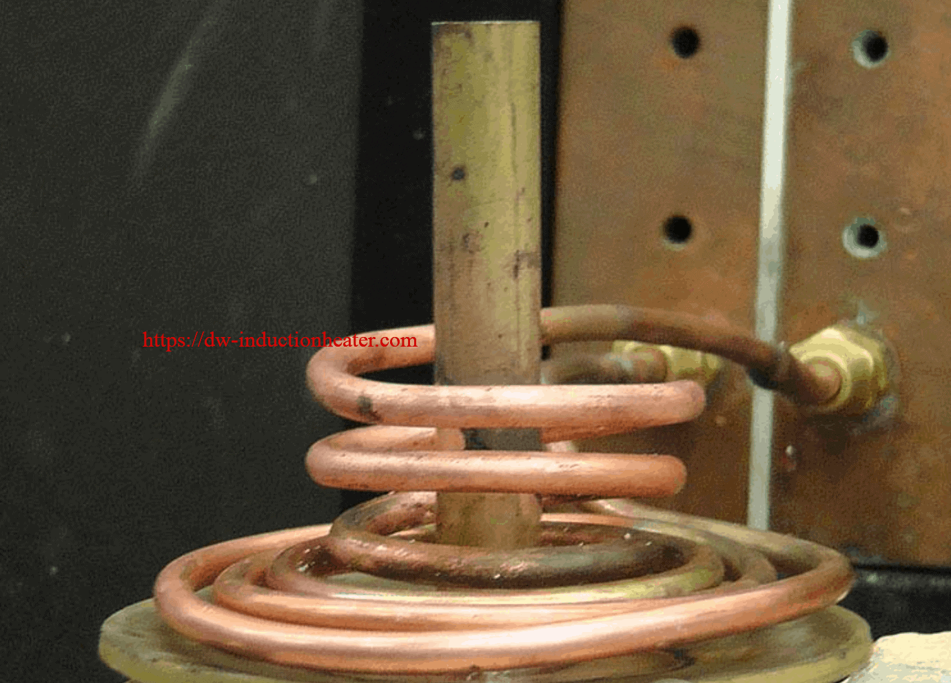
  3. A dual section/diameter coil was designed to uniformly heat the tube and plate to approximately 1500 0F at the interface of the parts – once temperature was to flow the alloy was reached, the pre-formed rings flowed around the tube and marker plated forming a complete braze filet. The apply was permitted to solidify, then the assembly was lowered out of the coil and subjected to a water bath to remove the residual flux residue.
Benefits of induction brazing:
  • Precise control of the time and temperature
  • Power on demand with rapid heat cycles
  • Repeatable process, not operator dependent
  • Safe heating with no open flames
  • Energy efficient heating

induction heating medical and dental applications

Induction heating medical and dental applications-induction heating systems for medical and dental industry

Induction heating is widely used within the medical and dental industries. Manufacturers of medical equipment benefit from induction heating technology. It provides clean, concise, repeatability, and is environmentally safe due to no open flame or toxic emissions. It is used in small laboratories as well as large production facilities. In recent years more and more medical research institutions are using induction heating for nanoparticle and electromagnetic hyperthermia treatment research. HLQ DW-UHF induction heating equipment is designed specifically with this application in mind. HLQ induction heating systems are used in many Universities and Research facilities around the world. How Induction Heating is used in the Medical & Dental Industries?
  • Nanoparticle and hyperthermia treatment research and testing
  • Induction casting of dentures and medical implants
  • Catheter tipping to form the tips of medical catheters
  • Sterilizing of connections in pharmaceutical or biomedical manufacturing
  • Heat treatment of memory alloys for medical applications
  • Needle and surgical instruments heat treating and heat staking
  • Medication or blood plasma heating for IV devices

Induction Heating systems are used in many processes within the Medical industries. The type of Induction heating applications you will find are catheter tip forming, dental drill bit brazing, plastic to metal bonding and many more.

There are many benefits to using Induction Heating within the Medical industry. The benefits are a very clean non contact heating process which is energy efficient and an extremely reputable heating process. Induction heating is a very fast way of heating your components in a consolable way. This will help improve your production throughput and improve Quality.

Induction coil solutions has many years of knowledge within the Medical industry supporting customers with new development work and helping with new coil designs for the new components. Induction coil Solutions has also helped many blue-chip companies with keeping they’re production lines running either with new replacement Induction Heating coils, or repaired Induction Heating Coils.

Medical and Dental Device Manufacturing Solutions

In today’s increasingly competitive global economy, medical device manufacturing companies are continually seeking ways to drive down production costs and accelerate time-to market. At the same time, improved product quality and manufacturing consistency are absolutely essential; there can be no shortcuts when a patient's life and well-being are at stake. Medical device manufacturers turn to advanced induction heating technology to help meet their production, cost and quality goals. Induction heating is a quick, clean, non-contact method of inducing heat for a wide variety of metal joining and heat treating applications . When compared to convection, radiant, open flame or other heating methods, induction heating offers substantial advantages.
  • Increased consistency with solid state temperature control & closed loop monitoring systems
  • Maximized productivity with in-cell operation; no soaking time or lengthy cool down cycles
  • Improved quality with minimized product warpage, distortion and reject rates
  • Extended fixture life with site-specific heat without heating any surrounding parts
  • Environmentally sound without flame, smoke, waste heat, noxious emissions or loud noise
  • Reduced energy consumption with up to 80% energy efficient operation
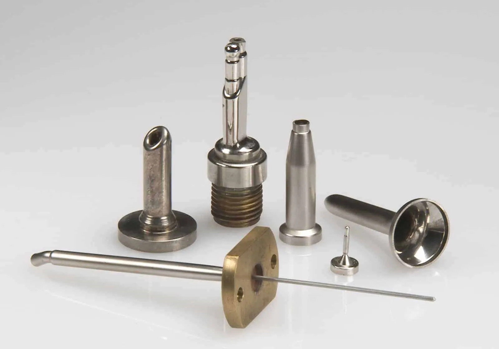
Among the many medical device manufacturing applications for induction heating: Annealing Incoloy Tubing In A Protective Atmosphere  With a 20kW power supply, induction heating can be used to heat steel tubing to 2000°F for annealing at a rate of 1.4 inches per second. Brazing Steel Orthodontic Parts  For this application we utilized an inert atmosphere to braze batches of orthodontic parts at 1300°F within 1 second Heat Setting Nitinol Medical Subtends  Induction heating was used to heat set medical stents on a mandrel to set proper size in two minutes at 510°C Brazing Three Joint Areas On A Dental Prophy Jet   With the right induction heating coil design, it is possible to braze three joints at once. In ten seconds, three joints on a dental prophy jet assembly were heated to 1400°F for brazing with improved yield consistency and reduced cycle time. Heat Staking A Threaded Brass Electrical Connector Into A Plastic Shell   Consistent, repeatable results were achieved at 500°F with a 10 second heat cycle. The electrical connector was firmly bonded to the plastic shell without any flashing or discoloration.

PWHT Insulation Blanket

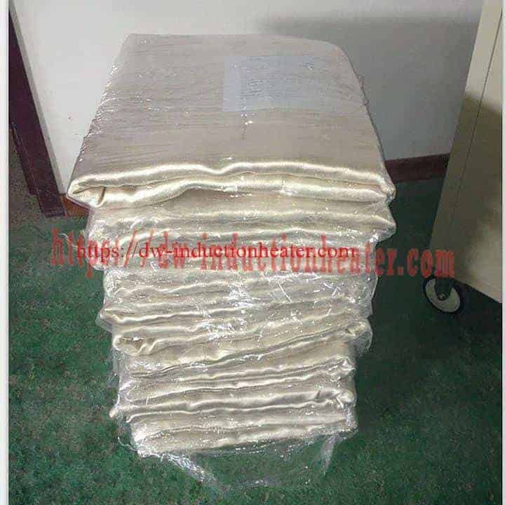
High Quality Oil pipeline PWHT insulation blanket material with best price is same as the heat treatment thermal insulation blanket.

Zirconia ceramic fiber thermal insulation blanket is easy installtion. The temperature is as max for 1100C. The size design as heating part. Insulation Blanket  

2021年10月28日星期四

Induction Catheter Tipping Heating

High Frequency Induction Catheter Tipping Heating Applications

This induction catheter tipping heating application is often needed in the Medical Industry for the manufacturing of catheter tubes.
With induction catheter tipping, RF energy raises the temperature on the stainless steel or brass mold, without physically contacting the mold or using an open flame. The tip of the catheter is then formed by inserting the plastic tubing into the heated die or mold to form the rounded edges. The rounded end of the catheter tube allows the tube to be safely inserted into the human with minimal trauma to body tissue. The mold will also have a wire that inserts into the tubing to prevent the formation of blockages. The precise and accurate temperature control capabilities of induction are ideal for this type of precise medical application. The molds are usually fitted with a water-cooled jacket used to cool the heated mold back to a defined start temperature which enables the induction system to be driven by a set time/cycle zone. Induction heating equipment for catheter tipping ensures a great degree of repeatability. The manufacturing process is fast and precise. Catheter tipping typically requires low power. HLQ has several low power units that are ideal for catheter tipping and will recommend the right equipment based on the parts and unique application requirements.   Heating Catheter Tipping Die Objective: To heat an aluminum catheter tipping die to above 2850F within 2 to 5 seconds for the forming of catheter material. Presently, heating is performed in 15 seconds with older induction equipment. The customer would like to use solid state induction heating equipment to reduce the heating times and develop a more efficient process. Material: Aluminum catheter tipping die measuring 3/8" OD and 2" long with a nonmagnetic sleeve over the heat zone. The catheter material was described as being similar to polyurethane plastic. Also, a 0.035" diameter steel wire was inserted into the catheter tube to prevent collapsing. Temperature: 5000F Application: The DW-UHF-3kW solid state induction power supply was determined to most efficiently produce the following results: --A heating time of 3.3 seconds to reach 5000F and form the catheter was achieved through the use of a two (2) over two (2) turn helical coil. --A quality catheter was formed by pressing 1/2" of the polyurethane tube into the mold while retaining shape through the use of a 0.035" wire to prevent collapsing of the tube. Laboratory results show that a substantial time decrease was accomplished which will allow for a significant increase in production while not sacrificing quality. Induction Heating Equipment: DW-UHF-3kWkW solid state induction power supply including a remote heat station containing one (1) capacitor totalling 1.2 µF. Frequency: 287 kHz

关注者

我的简介

我的照片
HLQ induction heating machine manufacturer provides the service of induction brazing,melting,hot forming,hardening surface,annealing,shrink fitting,PWHT,etc.